Minimizing Light Flicker in LED Lighting Applications
Abstract
Applying LEDs in offline retrofit lamps seems straightforward, but should be done with care to achieve similar light quality as the conventional lamp that the user is trying to replace. Light flicker is one of the aspects that need to be considered carefully during LED lamp design to avoid customer complaints from the field. This application note explains the LED lamp flicker phenomena in relation to driver topology and LED characteristics, and provides solutions based on several Richtek LED drivers in combination with specific LED strings. A practical flicker measurement method is explained as well, that can be used to measure light flicker in LED lamps.
Related Richtek LED driver parts mentioned in this application note: PFC flyback topology: RT7302, PFC Buck topology: RT8487, Linear topology: RT7321and PFC MR-16 LED driver: RT8479.
1. Characterizing Light Flicker in
LED Lamps
Quality indoor lighting requires evenly distributed light with steady light output and suitable color temperature. The human eye is sensitive to changing light intensity at lower frequencies, and fluctuating light intensity can lead to irritation, eye fatigue or headaches.
There are basically two kinds of light flicker that can occur in LED lamps:
- AC line
frequency related light fluctuation (usually at double the line frequency
(100Hz for 50Hz line frequency and 120Hz for 60Hz line frequency)
- Random light
intensity fluctuation (often caused by incompatibility between lamp and
peripheral lighting components)
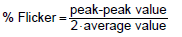
While flicker above 75Hz is not noticeable by most individuals, the perceptibility of flicker is not only related to frequency: it is also related to the intensity of the peaks and valleys of the light output (intensity modulation) and duration of these variations. Two quantification methods of this effect are shown in Figure 1:
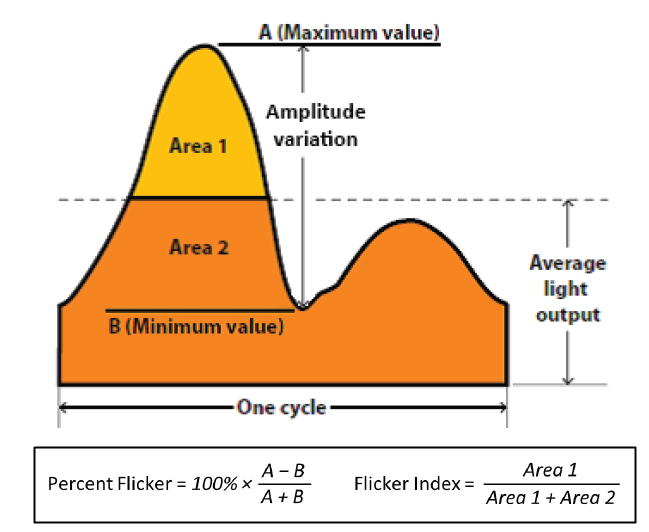
Figure 1. Flicker quantification methods (IES handbook 10th edition)
Measuring Percent Flicker is relatively simple and can be used for light sources that vary periodically, with relatively symmetric waveforms.
In light sources that have non-symmetric waveforms or show a-periodically flashing, the Flicker Index is a better way to quantify flicker, as it is able to account for differences in waveform shape (ie duty-cycle).
Conventional light sources are not without flicker: Incandescent lamps have relatively low flicker, their Percent Flicker around 10~20%. This is due to the long thermal time constant of the heated filament. Magnetically ballasted CFL lamps can have rather high flicker: Percent flicker from 37 ~ 70%. Modern electronically ballasted CFL lamps have low flicker: Percent flicker around 5%.
At this moment, no clear standard exists regarding maximum acceptable flicker in LED lamps, but many LED lighting manufacturers specify the percent flicker to be less than 30% in the 100Hz - 120Hz frequency range.
LED light output is directly related to the current through the LED, and by nature LED light output reacts instantly on changing LED current conditions. Stable LED driving current is therefore the main criteria to achieve flicker free operation in LED lamps.
2. Relation between Flicker, LED
Current and LED Voltage Ripple
In order to determine the relation between light flicker, LED current ripple and the LED driver output voltage ripple, the LED string characteristics need to be examined.
Figure 2 shows the relation between LED current and relative luminous flux of a Cree XLAMP MX-6 LED high brightness LED.
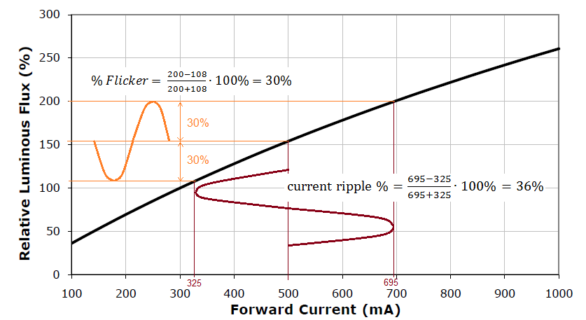
Figure 2. Extrapolating LED current ripple to luminous flux variation for a Cree high brightness LED
A sine shaped LED current ripple is drawn in the graph, and the resulting luminous flux variation is extrapolated. So changing LED current has an immediate effect on the light output, but it can be seen that the curve is not exactly linear. The relation between LED current ripple and resulting flicker % is therefore not linear either, and for most LEDs, the % light flicker is lower than % current variation.
In most offline LED drivers, the circuit parameters control the output (LED) voltage ripple, and the LED current ripple is a result of the output voltage ripple. Therefore it is important to know the relation between the voltage ripple across the LED string and the current ripple through the LED. This relation can be found from the LED I/V curve in Figure 3. (The same Cree XLAMP MX-6 LED)
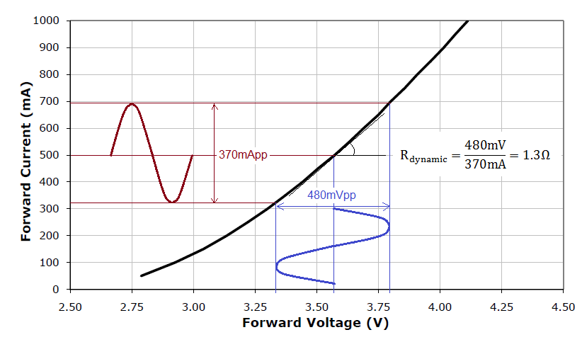
Figure 3. LED I/V curve with dynamic resistance measurement
The dynamic resistance of the LED at a certain operation point will determine the relation between the voltage ripple on the LED and the resulting current ripple thought the LED. This dynamic resistance is quite small, which means that a very small voltage ripple can already result in large current ripple. Since the slope of the I/V curve changes at different operating points, the dynamic resistance needs to be determined around the average LED current operating point.
Most LED lamps use multiple LEDs. When placing LEDs in series, the dynamic resistance needs to be multiplied by the number of LEDs. When paralleling LEDs, the dynamic resistance needs to be divided by the number of LEDs in parallel.
3. Offline LED Driver Basic Circuit
To understand the reason behind 100Hz/120Hz flicker in offline LED lamps, it is important to understand the basic operation of the mains fed LED driver. The basic circuit is shown in Figure 4:
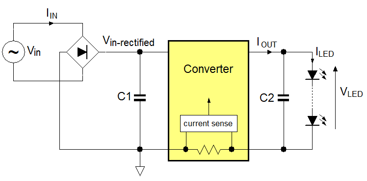
Figure 4. Basic offline switching LED driver
In most single stage offline LED drivers, the converter consists of a Buck, Buck-Boost or flyback converter to convert the (rectified) line voltage into a suitable output voltage for driving the LED string. The main feedback loop is LED current sense, to provide a constant (average) current to the LED string.
For flicker-free operation, the LED current ILED needs to be a stable DC current, and the LED voltage VLED will thus be a fixed DC voltage. Since the line voltage is a sine-wave, the circuit must contain at least one voltage buffer element to transform alternating current into DC voltage. This can be either C1 or C2 in Figure 4.
Low power factor applications:

Figure 5. Low power factor converter
Choosing C1 as the buffer element (large value for C1 as in Figure 5) will provide a relatively stable DC input voltage for the converter, and with fast current feedback control loop, the output current IOUT will be stable as well. C2 will only be needed to filter the high frequency switching noise of the converter, and can be a relatively small value. Line frequency content in the LED current will be small, which leads to low 100Hz/120Hz flicker. However, choosing a large value for C1 will result in pulse shaped input currents, leading to poor power factor and the line current IIN will have high harmonic distortion. This solution is normally only selected in low power (<6W) LED driver applications.
High power factor applications:
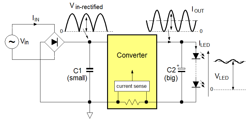
Figure 6. High power factor converter
Most higher power LED lamps nowadays require good power factor with low input current harmonics. This means that C1 value must be kept small as shown in Figure 6, and the converter must try to maintain a sine shaped input current as well, requiring a low bandwidth control loop. The output current of the high PF converter can be approximated by a sine2 function, which is a cosine waveform with double frequency and the average LED current as mean value. The voltage buffer element is now C2, and it is used to reduce the voltage ripple across the LED string. Obviously, to achieve very small LED voltage ripple will require very large values for C2. Output voltage ripple together with LED characteristics will determine the LED current ripple and subsequent 100Hz/120Hz flicker of these LED lamps.
The design method for controlling flicker in high PFC single stage LED drivers is as following:
a.Define the max flicker percentage requirement (usually around 30%)
b.Determine the maximum LED current peak to peak variation ILED_PP from the Luminous Flux vs forward current curve
c.Determine the dynamic resistance RDYNAMIC_TOTAL of the LED at the operation point from the LED I/V curve
d.Determine the maximum voltage peak to peak ripple VOUT_PP across the total LED string:

e.Determine the required output capacitor value :
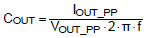
where:
IOUT_PP is 2x the average LED current (good approximation for a high PF converter)
VOUT_PP is the allowed peak to peak output voltage ripple across the LED string
f is double the line frequency.
The following chapters show several examples for offline LED drivers, designed for specific flicker percentage. Calculations and measurements are explained, and some solutions to reduce LED flicker are discussed.
4. 20W Isolated High PF LED Driver
using RT7302
RT7302GS is a constant current Flyback LED driver using primary side regulation and constant ON time topology to obtain high power factor. The converter switches in boundary conduction mode.
The below picture shows a reference design for a 20W T8 application. Max light flicker is defined at 30%.
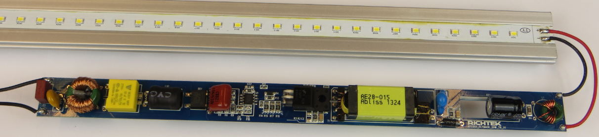
Figure 7. RT7302 Reference design board with narrow form factor for T8 application
The long T8 luminaire for this 20W T8 design as shown in the picture consists of 8 LED strings in parallel. Each string consists of 16 LEDs in series. The LED type is Edison Opto PLCC 3022 0.2W series. The total LED string combination has a forward voltage of 49V at 400mA current. Each LED string will thus receive 50mA current.
Figure 8 below shows the graphs from the LED specification that can provide the means to derive the allowed current ripple and dynamic resistance of the LED string assembly.
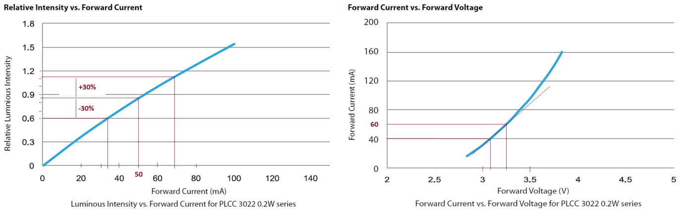
Figure 8. Graphs from PLCC3022 low power LED
From the luminance vs current graph: For 30% light flicker, the LED current may vary +/- 17.5mA or 35%. For the total string assembly (8 strings in parallel), the LED current peak to peak value can be 280mApp
From the I/V curve: The dynamic resistance of one LED around the 50mA operation point is 7.5Ω. The dynamic resistance of the total LED string assembly is 7.5*16/8 = 15Ω
The allowed voltage ripple across the total string combination can be calculated:

The circuit diagram of the 20W LED driver is shown in Figure 9. This is a high PF design. This means that the output current in the secondary winding will have a high content of low frequency ripple, with a frequency which is double the line frequency. The main buffer element is output capacitor EC1.
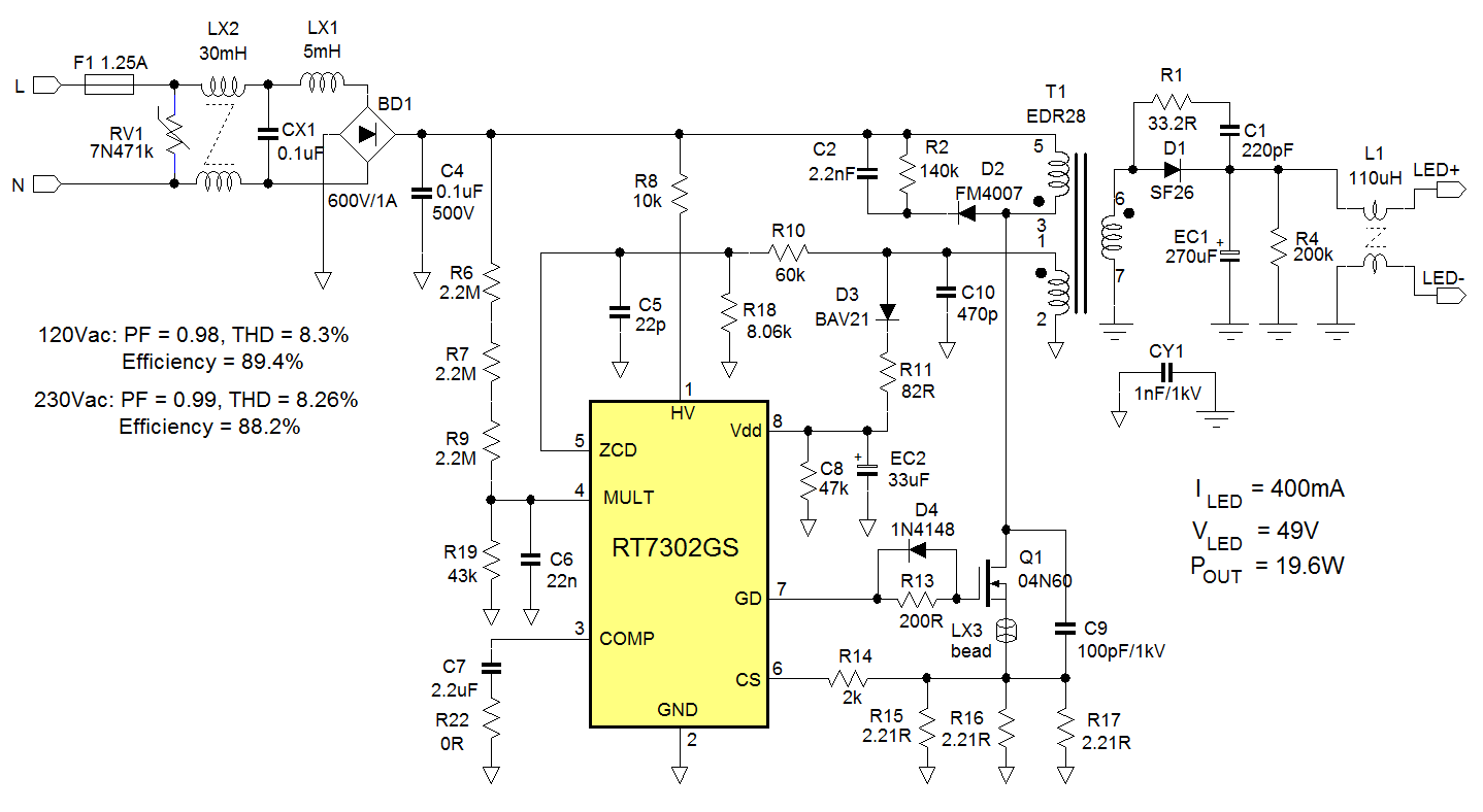
Figure 9. RT7302 20W Isolated high PF LED driver
For a 50Hz line frequency design, the output capacitor value can be estimated by:
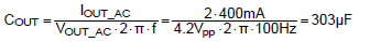
A 330µF capacitor was selected for EC1.
Figure 10 below shows the measurements of the converter output current, LED voltage, LED current and light output at 230V/50Hz input and using a 330µF output capacitor.
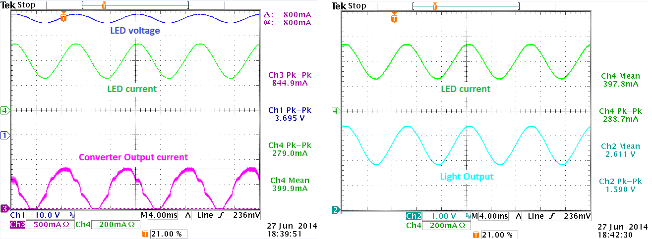
Figure 10.
The purple waveform is the converter output current with all high frequency switching removed. The amplitude is double the average LED current and it has a frequency of 100Hz. The LED voltage ripple is 3.7Vpp, due to the larger output capacitor. The average LED current is 400mA with ripple of 279mApp, which is 34.8% ripple. The dynamic resistance of the LED assembly is slightly lower than calculated from the LED graphs: 3.7V/279mA = 13.6Ω.
The scope plot on the right side shows LED current and measured light output (light measurement done with the self-made light sensor, see chapter 9). The LED current ripple is 34.8%, the measured flicker is 30.4%, very close to the required value.
5. 10W Non-isolated High PF LED Driver using RT8487
RT8487 is a high power factor LED driver controller that can be used in non-isolated Buck and Buck-Boost applications. The controller uses resonant switching in boundary conduction mode. The below application example shows a 10W design using sixteen Cree XLAMP MX-6 LED in series for 49V LED string voltage.
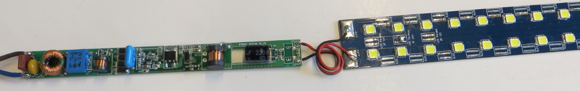
Figure 11. RT8487 Non-isolated 10W high PF LED driver
The driver is designed for 200mA average output current. The % flicker is set at 30%. The LED ripple current and voltage can be derived from below graphs.
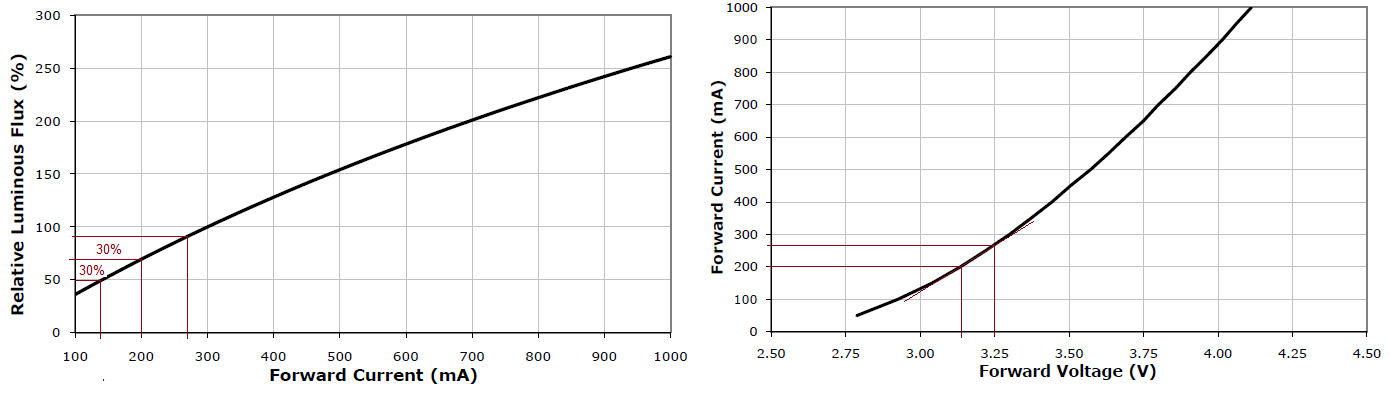
Figure 12. LED characteristics for Cree XLAMP MX-6
From the luminance vs. current graph: For 30% light flicker, the LED current may vary +/- 70mA or 35%.
From the I/V curve: The dynamic resistance of one LED around the 200mA operation point is 1.7Ω. The dynamic resistance of the total LED string assembly is 1.7*16 = 27.2Ω (note that the dynamic resistance of the LED is higher in the low current range). The allowed voltage ripple across the total string combination can be calculated:

Figure 13 shows the LED driver schematic. RT8487 is used in Buck topology with floating controller. A bootstrap circuit provides the IC supply, and the circuit only uses standard drum coil inductors.
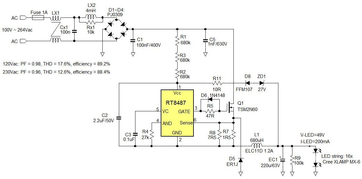
Figure 13. RT8487 10W high PF design in floating Buck topology
For a 50Hz line frequency design, the required output capacitor value can be estimated by:
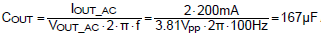
A 220uF output capacitor was selected for EC1.
Figure 14 shows the output measurements for this converter.
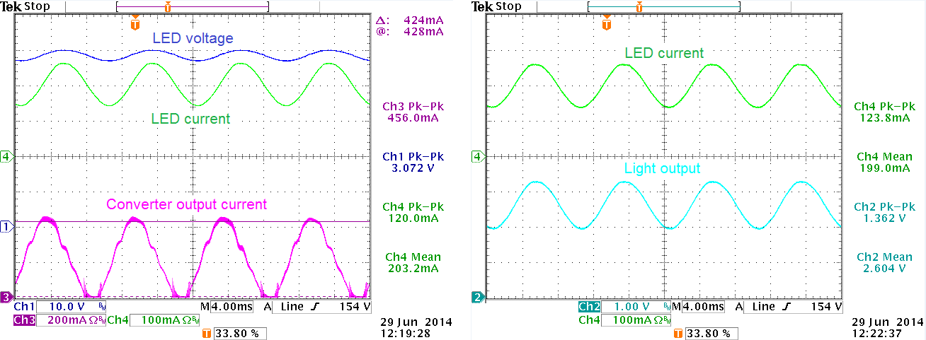
Figure 14.
The purple waveform is the Buck converter output current with all high frequency switching removed. The AC amplitude at 424mApp is slightly higher than double the average LED current. The LED voltage ripple is 3.07Vpp, a bit lower than the originally calculated value due to the larger output capacitor. The average LED current is 200mA with ripple of 120mApp, which is 30% ripple. The dynamic resistance of the LED assembly is slightly lower than calculated from the LED graphs: 3.07V/120mA = 25.6Ω.
The scope plot on the right side shows LED current and measured light output (light measurement done with the self-made light sensor, see chapter 9). The measured flicker is 26.1%, well below the max requirement.
From the previously discussed examples, it is clear that single stage high PFC designs will generate some line frequency related flicker. The amount of flicker depends on line frequency, converter output current AC amplitude, output capacitor size, and the luminance-current characteristics and dynamic resistance of the LED string. The output current shape of the converter depends on power factor.
To reduce the 100/120Hz flicker in single stage PFC LED drivers, the LED current ripple must be reduced. There are several possibilities to do this:
1.Reduce the peak to peak amplitude of the converter output current. This can only be a achieved by reducing the power factor of the design, by increasing the input capacitor, and increasing speed of the current feedback loop. PF and THD may not meet the requirements, and this solution is normally only used for low power designs.
2.Increasing the output capacitor. To reduce the ripple to very low levels, a very large capacitor is needed, which increases cost and size.
3.Increasing the dynamic resistance of the LED string: choosing LEDs with higher RDYNAMIC, or operating the LED in the lower region of the I/V curve. One could also place a resistor in series with the LED string, but this will add extra losses and reduces the converter efficiency.
4.It is also possible to use a linear post regulator to remove the output ripple, thereby minimizing the LED current ripple. A simple circuit solution is shown in Figure 15.
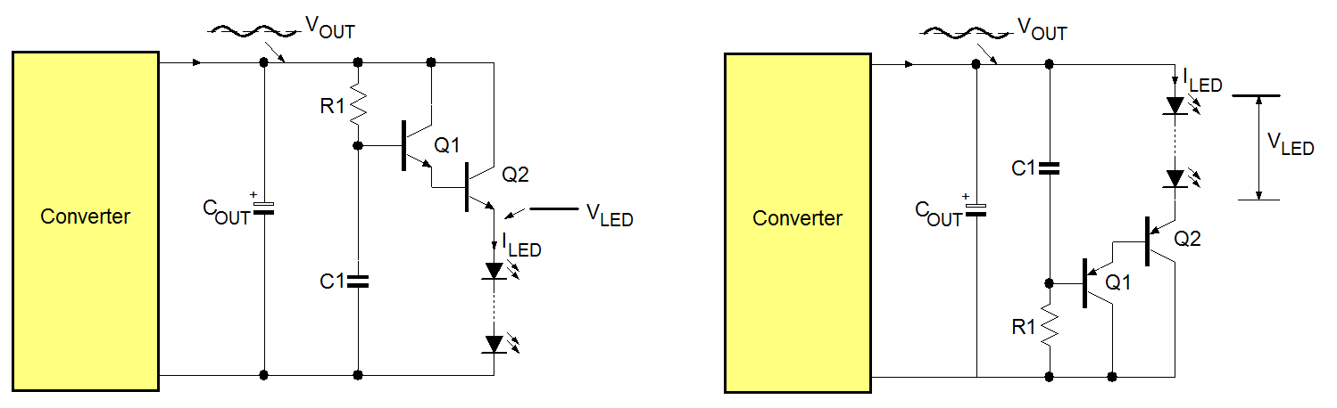
Figure 15. LED ripple remover circuits, using NPN or PNP transistors
The circuit is a self biasing emitter follower. A Darlington configuration is used to keep the impedance of the base resistor relatively high, so a small capacitor can be used to filter the 100Hz ripple. The circuit can be placed at VOUT using NPN transistors, or at GND, using PNP transistors.
The addition of this circuit will reduce the LED current ripple to very low values, close to 0%. The drawback of the LED current ripple remover circuit is the extra dissipation in Q2, which reduces the efficiency of the LED driver. The dissipation in Q2 can be estimated by (VOUTPP/2 +1.2V)*ILED .
Figure 16 shows the LED ripple remover circuit tested with the 10W LED driver. The zener diode ZD2 is added to speed-up the charging of the filter capacitor during start-up.
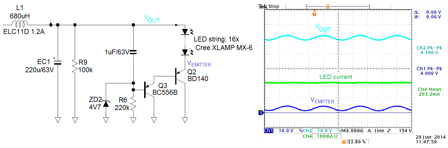
Figure 16. Ripple remover circuit applied to the 10W design
After implementation of the ripple remover circuit, the LED current is completely flat, and flicker free. For the 10W LED driver design, the dissipation in Q2 is around 0.63W. The efficiency of the driver drops from 89% to 84.5%. Due to the relatively high dissipation, the ripple remover solution is only suitable for lower power designs.
Flicker free operation in high power LED drivers:
For high power LED drivers that require flicker free operation, a two-stage design is needed: this can be an isolated PFC flyback with separate Buck stage at secondary side or a non-isolated PFC Boost + Buck, see examples in Figure 17.
|

|
|
Figure 17. Isolated PFC Flyback with CC Buck
|
Non-isolated PFC Boost with high voltage CC Buck
|
7. Reducing Light Flicker in Linear Offline LED Drivers
Due to the availability of low cost high voltage LEDs, linear offline LED drivers are becoming more popular. Richtek linear LED drivers RT7321 & RT7322 for medium powers are using four high voltage LED strings that are dynamically connected in parallel or in series, thereby increase LED usage over the full mains cycle. See Figure 18.
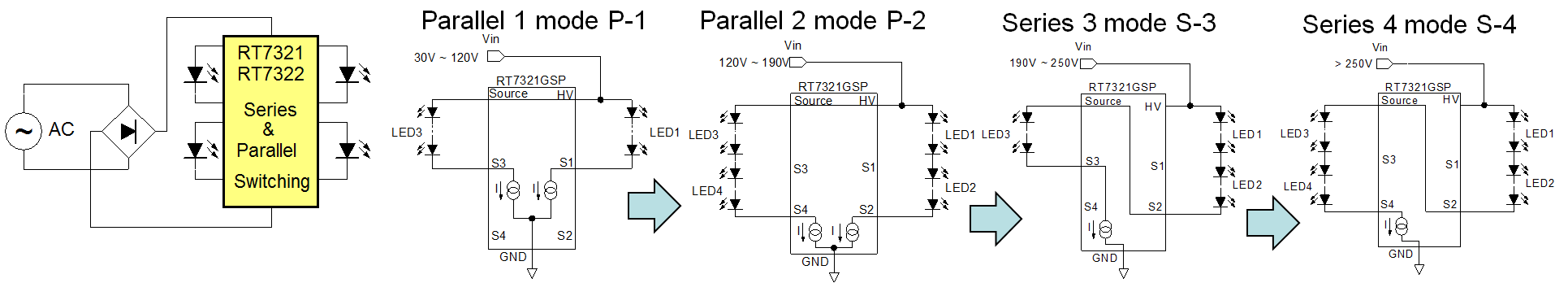
Figure 18. RT7321(230V)/RT7322(110V) linear LED driver with series/parallel LED string switching
Since the circuit does not contain any voltage buffer element, it is obvious that the LED current cannot be continuous over the full mains cycle: at the sine wave zero crossing, the LED current will drop to zero for a certain time. This will result in flicker, but the light output variation is not sinusoidal. The normal % flicker quantification is not really suitable for this type of LED driver. An example will help to clarify this.
Figure 19 shows a 7W linear LED driver design using RT7321CCGSP and Philips Lumiled high voltage LEDs.
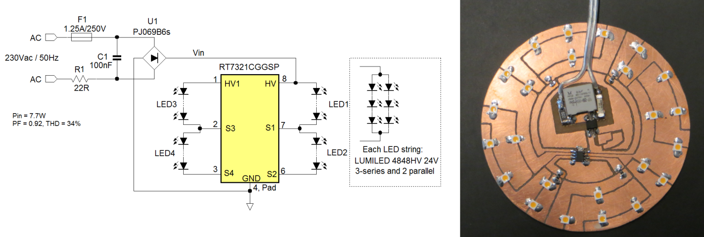
Figure 19. RT7321CCGSP 7W design
RT7321CGGSP will provide 20mA in parallel mode and 40mA in series mode. Each LED string uses three 24V LEDs in series and two strings in parallel to stay within the current rating of the LEDs. Each string will have approximately 72V forward voltage, which is a suitable value for RT7321 230V application. The circuit needs a small X-capacitor and series resistor for EMI purposes. All components can be mounted on the LED board. Measurements in figure 20 show the combined total LED current and light-output of this 7W design.
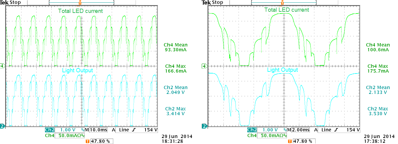
Figure 20. Combined LED current and light output of the RT7321 7W design
It can be seen that this design creates big LED ripple which goes to zero when the rectified input voltage drops below the LED string voltage. Calculating percent flicker will always result in 100% flicker. But since the waveform is not sine shaped, flicker index can be used instead.
The areas above and below the average value can be measured. It was found that the flicker index of this waveform is around 0.28, which is still a relatively large value.
It is possible to reduce the flicker of this design by adding a small buffer circuit. But since this linear driver design is intended to provide reasonable power factor, simply adding a big input capacitor is not a suitable solution. It is possible to add a valley fill circuit using small film capacitors, which provides sufficient buffering to keep LED1 and LED3 active during the sine wave zero crossing, and keep the power factor at an acceptable value. Figure 21 shows the circuit solution.
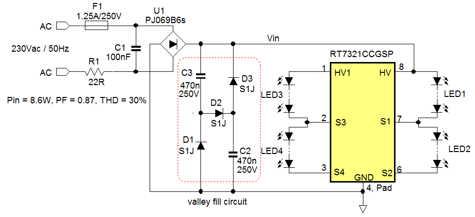
Figure 21.
Since the valley fill buffer capacitors don’t see the full rectified line voltage, 250V types can be used. The diodes and film capacitors are small enough to fit on the LED board. Power factor is still acceptable at 0.87.
The measured combined total LED current and light-output of this solution are shown in Figure 22.

Figure 22. Combined LED current and light output of the solution with valley fill circuit
It can now be seen that the LED current and light output stay continuous during sine wave zero crossing. The flicker index for the light output waveform is now around 0.2. Of course it is not as good as active switch-mode solutions, but for many applications that require very small form factor, it will be an attractive alternative to switch-mode LED drivers.
In some LED lamp applications, random flicker can occur. This random flicker shows as intermittent light variation with a frequency not necessarily related to the line frequency. This kind of flicker often happens when the LED lamps are used in combination with existing lighting peripherals like dimmers or electronic transformers.
Most existing lighting equipment was designed for traditional incandescent or halogen lamps, which behave as resistive loads with relatively high power consumption. Most LED lamps do not behave as resistive load, and due to their higher efficiency, they consume much less power. When they are connected to the equipment, the circuits may malfunction, or work intermittently. This causes the lamp to flicker. To find a solution for this, the basic circuit function of the peripheral equipment has to be understood and some adoptions need to be made to the LED lamp circuit to make it suitable to be used in combination with the equipment.
As an example, an MR-16 application is examined. Figure 23 below shows the typical MR-16 lamp application and its electrical equivalent.

Figure 23.
The electronic transformer circuit is a self-oscillating resonant half-bridge converter. The power transistors are driven by a small transformer which is in connected series with the output transformer, to obtain load proportional base drive current. These circuits work very well with resistive loads, which provide a stable defined load current. Due to the transistor load dependent drive, the circuit needs a minimum load current to start up. Halogen lamps with power ranging from 20W to 60W satisfy these conditions.
When connecting LED lamps to electronic transformers, all kinds of incompatibility problems can happen:
1.The LED lamp input rectifier stage does not resemble a resistive load at all; it behaves more like a capacitor.
2.The LED lamp lower power consumption is not sufficient to guarantee stable start-up of the electronic transformer circuit.
3.The capacitive load can cause high current spikes, which can trigger the electronic transformer over-current protections, and can result in repeated shut-down/re-start cycles.
Figure 24 below shows a typical low cost MR-16 LED lamp, consisting of a rectifier stage and a Buck LED driver, connected to an electronic transformer. The scope plot on the right shows the related waveforms.
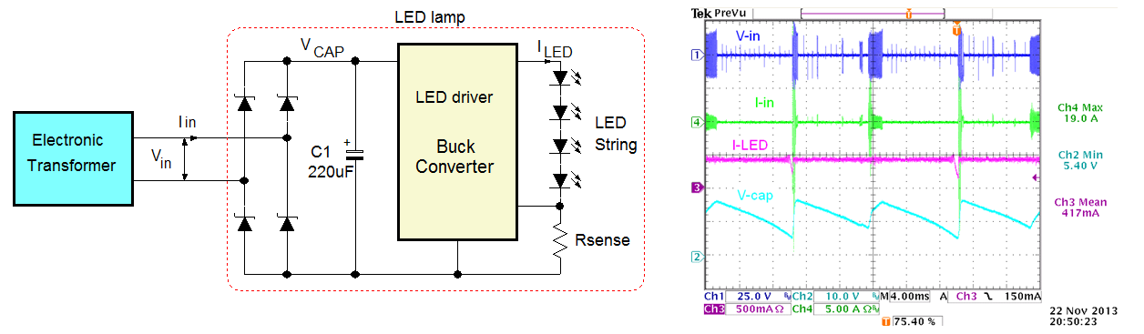
Figure 24.
In theory, the 12Vac output voltage of the electronic transformer should be sufficient to charge VCAP to 16~17 Vdc, and the Buck LED driver should have sufficient input voltage to provide a constant current to the four LEDs. But in reality, it can be seen that the electronic transformer is only active for short periods. The LED lamp capacitive load cannot provide a stable operation of the electronic transformer, and the buffer capacitor is only occasionally charged with high current pulses. Due to this intermittent behavior, the input voltage of the Buck converter occasionally falls below the LED string forward voltage, and LED current shows a dip. This results in random low frequency flicker, which is very clearly visible. Note: Some electronic transformers are more sensitive to capacitive loads than others. A LED lamp may work better with simple electronic transformers without protection features. But in general, many low cost LED lamps will show compatibility problems when connected to various electronic transformers.
To solve this incompatibility problem, the LED lamp needs to be re-designed to make it behave more like a halogen lamp: The input current must be stable and must satisfy the minimum operation current of the electronic transformer.
Richtek has developed special MR-16 LED drivers to achieve optimal electronic transformer compatibility. These LED drivers use a two stage design topology: see figure 25:
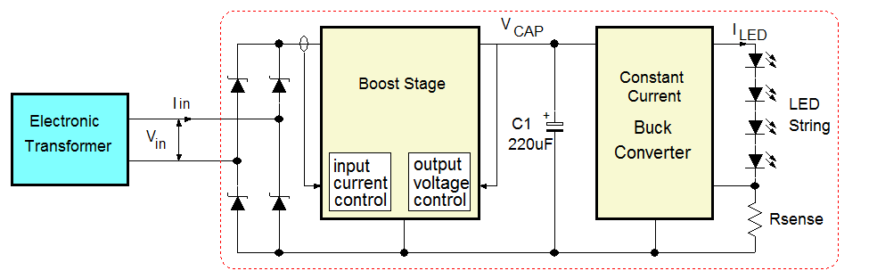
Figure 25. Two stage MR-16 LED driver topology
The first stage is a Boost converter with input current control and output voltage control. The second stage is a constant current Buck converter. The Boost stage will control the input current level to satisfy the minimum load requirement of the electronic transformer, and provide a PFC function by keeping the electronic transformer active over the full mains cycle. The input impedance will resemble a resistive load. The Buck stage is fed from the Boost output voltage where C1 is the buffer element. This Boost voltage is stable and high enough for stepping down to LED strings up to 5 high brightness LEDs in series.
Figure 26 shows a typical 5W MR-16 application using RT8479C, which is a fully integrated 2-stage MR-16 LED driver. The LEDs used in this design are four Philips Lumiled Luxeon Rebel LEDs connected in series.
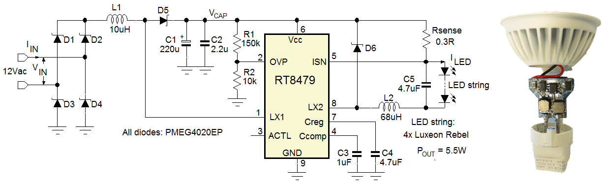
Figure 26.
RT8479C contains two integrated power MOSFETs: one for the Boost (LX1) and one for the Buck (LX2). The Boost operates as fixed off time peak current control, which provides a defined minimum input peak current and natural PFC current modulation. The bus voltage is regulated by the Boost and includes an overvoltage protection. The Buck is a fast hysteretic constant ripple current topology and regulates the LED current to a stable flicker free level via a high side sense resistor. ACTL can be used to control the LED current via an external dimming signal or allows for temperature controlled current fold-back via an NTC resistor.
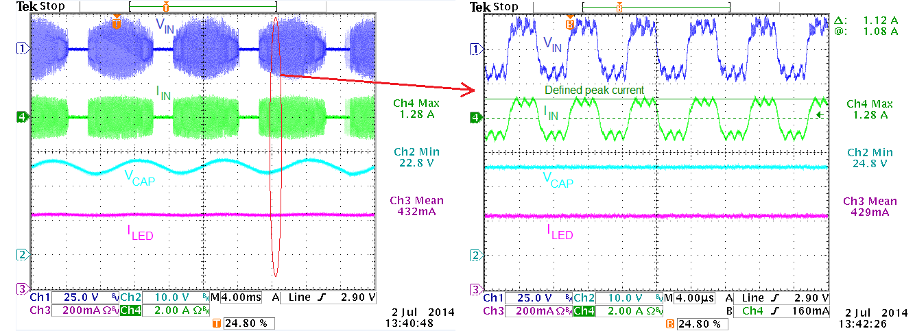
Figure 27. RT8479 Two-stage MR-16 input and output waveforms
Figure 27 shows the input and output waveforms of the RT8479 LED driver when connected to an electronic transformer. The electronic transformer is active over a large portion of the line voltage period. (Only during sine wave zero crossing, the circuit has a small inactive time due to the DIAC triggered start-up). The zoomed waveforms on the right show the combined transformer switching cycle and the super imposed Boost stage switching: The Boost input current control keeps the input peak current at a defined level which is sufficient to keep the transformer circuit active. The Boost also regulates the bus voltage VCAP to a 25V level which gives sufficient headroom for the Buck stage to drive the four LEDs with stable, ripple free current. Another advantage of this operation mode is that the input power factor is quite high, around 0.97, and the absence of high current spikes improves the reliability of the complete application.
Although measuring LED current variation will provide some indication of LED flicker, it is better to measure the actual light variation of the LED string. Since only the relative light variation needs to be measured for calculating flicker percentage, a simple photo sensor with build-in amplifier can be used. The output waveform can be show on the oscilloscope.
The schematic in Figure 28 shows a simple light to voltage converter using the TSL257 IC.
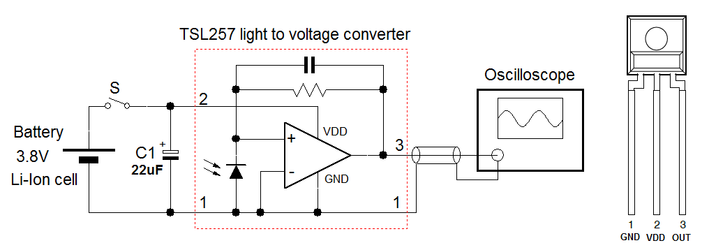
Figure 28. Light flicker measuring tool
The TSL257 is a simple light to voltage converter IC with good linearity. It can be powered from a single Li-Ion cell, making it a portable measurement tool. The output voltage is directly proportional to the light intensity (irradiation) and can be connected to an oscilloscope, thereby showing the light fluctuation as a waveform on the scope screen. The 2kHz bandwidth is sufficient for light flicker measurements. TSL257 is not expensive, and can be bought at Farnell or Digikey.
The following pictures show how to build such a tool.
Required components: coaxial wire, Li-ION battery, TSL257 IC, a switch, a 22uF/25V electrolytic capacitor and a black plastic box with a 3mm hole drilled in the top. The TSL257 is placed with the sensor towards the hole.
Then the sensor is fixed with non-transparent epoxy glue. Finally the other components are connected.
Due to the high light sensitivity of the TSL257, the incoming light to the sensor needs to be attenuated considerably to make it suitable to for measuring direct light from LED strings. Several layers of A4 paper can be placed over the hole to achieve sufficient light attenuation. For the test tool, 8 layers of paper were used.
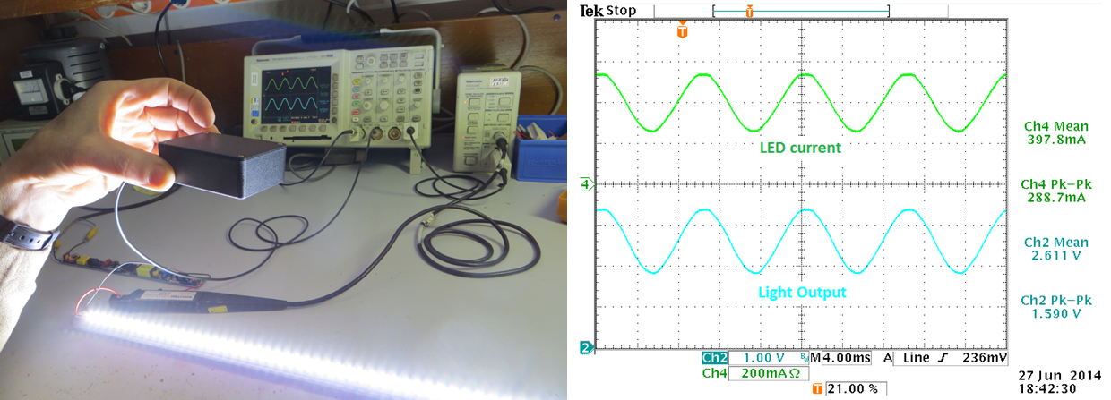
Figure 29. Practical light flicker measurement
To avoid ambient light influence, the room lights should be switched off. The tool should be positioned above the LED light to achieve a light output reading with the maximum level around 3V. When waveform clipping occurs, the distance to the light should be increased, or more layers of paper should be added for more light attenuation. Measure the peak-peak and average value of the sensor output. Apply some averaging for noise reduction. For sine wave signals, the % flicker can be calculated from:
Minimizing light flicker in LED lamps starts with a good understanding of the driver topology and the LED characteristics. For single stage high PF LED drivers, light flicker can be quantified, measured and reduced by suitable component selection or adding LED ripple reduction circuits. Most random flicker is caused by compatibility problems between LED lamp and peripheral lighting equipment. Thorough analysis of these systems is required to solve these flicker problems. Richtek provides several powerful offline LED driver solutions which exhibit good system compatibility and fulfill the light flicker requirements of today’s LED driver market.