Understanding the characteristics of Li-ion batteries and Richtek power management solutions
Preface
Lithium-ion/polymer rechargeable batteries, which have been widely used today, have distinguished properties, but are very delicate and have to be used with extreme care. Improper use of Li-ion batteries will bring about catastrophic consequences. The incidences of burning and explosions of Li-ion batteries have often been heard. Carefully understanding their properties and adopting a right battery management method is most essential for making good use of Li-ion batteries.
The Properties of Li-Ion/Polymer Batteries
It may not be easy to have a comprehensive understanding of one thing, because different points of view may lead to different ultimate understandings. A few but important perspectives, which may affect the charge strategies, will be taken to investigate the properties of Li-ion/polymer batteries. The following diagram describes the relationship between the cell capacity and the cycle life with various Li-ion battery charge voltages with the cell capacity rated around 950mAH.
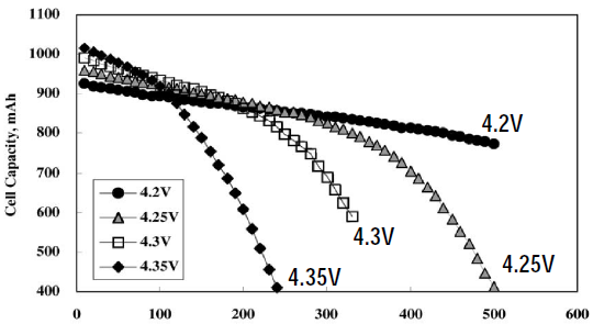
Figure 1. Relationship between the cell capacity and the cycle life with various Li-ion battery charge voltages.
From the diagram, higher charge voltages boost initial capacity, but results in lower cycle life; vice versa.
The diagram below describes the relationship between cell capacity and cycle life of a battery at various discharge currents.
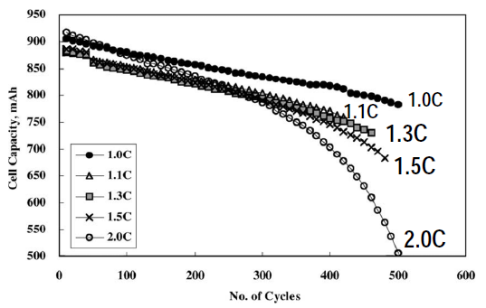
Figure 2. Relationship between cell capacity and cycle life of a battery at various discharge currents.
It can be seen from the diagram that higher discharge currents make cell capacity decay faster and cycle life become shorter; vice versa.
In the same way, it can also be found that Li-ion/polymer batteries are neither suitable for very high charge currents, nor suitable for being deeply discharged. Any extreme battery behaviors will bring a detrimental effect on cell capacity and cycle life. Balance is essential in using Li-ion/polymer batteries, which means that all the factors must be kept in balance to ensure successful usage.
Environment also has tremendous influences on Li-ion/polymer batteries. In fact, temperature has the greatest impact. The following diagram shows how temperature may affect the battery characteristics.
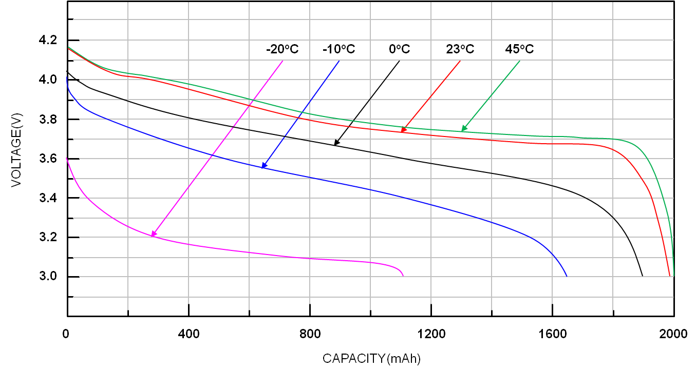
Figure 3.
At higher temperatures, Li-ion/polymer battery capacity increases, so does charge voltage. When temperature decreases, especially at very low temperatures, electrical energy can neither be discharged from, nor charged into batteries, so it is seen that charge voltage is decreased significantly and cell capacity is reduced drastically.
With all the knowledge of these properties, the strategy in managing Li-ion/polymer batteries can be readily determined.
The Protection of Li-Ion/Polymer Batteries
The first step to utilize Li-ion/polymer batteries is to make sure they are under protection: from over-charge or over-discharge. Although there may be other protections, the protection circuit will serve as the ultimate protector for Li-ion/polymer batteries. What the protection circuit covers are over-voltage protection, over-current protection and under-voltage protection, where over-current protection is bi-directional, i.e. for over-charge and over-discharge. The following diagram, from the RT9545 datasheet, is the application circuit of the Li-ion battery protector.
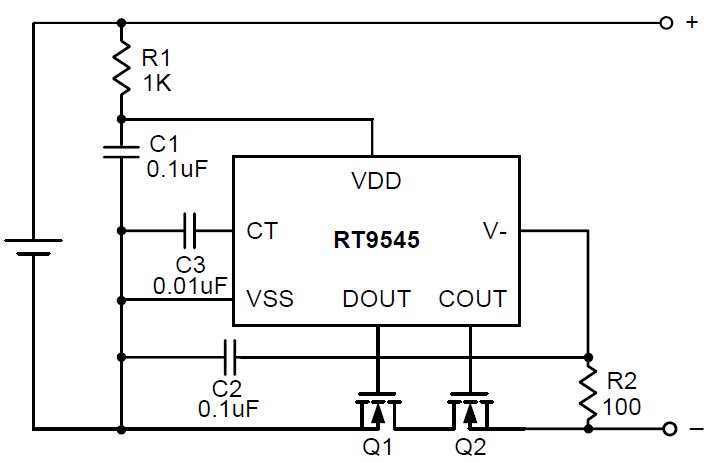
Figure 4. RT9545 application circuit
In general applications, both a protection IC and a battery are placed together in a battery pack. End users can only access the two electrodes, + and –. In the protection circuit, the MOSFETs, Q1 and Q2, are switches used for protection control, and are also current-sensing devices. When the IC detects the voltage drop across the switches is too large, it will shut down the current through the battery by making the MOSFET into cut-off state in order to protect the battery. Moreover, since the battery current is sensed by way of detecting the differential voltage across the MOSFETs, the turn-on resistance of the MOSFETs will be an important parameter and will need special attention from designers of battery-powered systems.
The detection of an over-voltage state or an under-voltage state is accomplished by measuring the voltage difference between VDD and VSS. Most of the users will choose 4.35V and 2.5V as over-charge and over-discharge protection threshold voltage, respectively. These threshold voltages may be set differently, depending on the types of batteries.
The following diagram is the RT9545 functional block diagram, shown for the reference of interested readers.
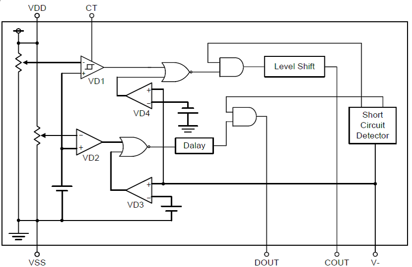
Figure 5. Functional block diagram of RT9545
Charge Strategies and their Relationships with Temperature
Based on the knowledge of the Li-ion/polymer battery properties, the industry has formed a three-stage Li-ion battery charge algorithm: pre-charge stage, constant current charge stage, and constant voltage charge stage. In a pre-charge stage, a battery is adjusted to prepare for fast charging with a large current. In a constant current charge stage, electrical energy is quickly restored back to the battery. In a constant voltage charge stage, a battery is going through the final adjustment so that the cell capacity can be maximized. The charge process of this stage is in full accordance with the need of the battery itself, in contrast with that the battery, in a constant current charge stage, is under a strong external force (electric field). The following diagram illustrates how charge works in the three charge stages, and their corresponding voltage and current curves.
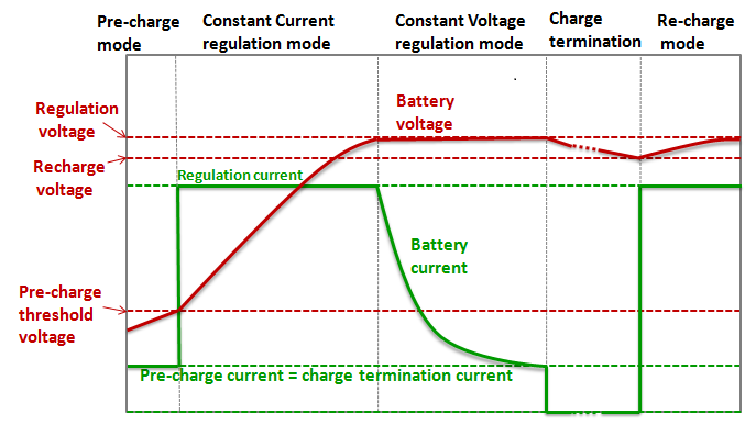
Figure 6. Li-ion battery three charge stages.
If the battery voltage is lower than a predetermined threshold, usually 2.8V~3V for most of the Li-ion batteries, the charger will enter a pre-charge stage, during which charge current is set under C/10. During a constant current charge stage, charge current is usually set at around 1C, which is the current by which the cell capacity drops to 80% of its original value after 500 charge/discharge cycles. During a constant voltage charge stage, charge current gradually drops to a predetermined level, usually C/10. And when it happens, the charging process will be terminated.
Recharge stage actually consists of a constant current stage and a constant voltage stage. During a recharge stage, the charger can compensate for the capacity drop, caused by self-discharge of the battery or other battery-connected loads. It is intended to keep batteries as fully charged as possible at the moment the batteries (and the system powered by them) are disconnected from chargers.
The first thing that a charge management device considers to handle the effect of temperature on a Li-ion/polymer battery is to inhibit battery charging if the battery temperature is too high or too low. This requires battery temperature detection, which can be accomplished with a thermistor. A typical application circuit of the RT9503A is shown below, where the variable resistor, placed together with the battery, is a thermistor. A current source of 102mA flows out of the TS pin of the RT9503A and through the thermistor, across which a voltage is established. If the voltage falls outside of the range of 0.5V~2.5V, charging will be terminated immediately in order to protect the battery from damage due to being charged under improper temperatures. With the current mentioned above, and the TS voltage specified in the datasheet, the specification of a thermistor can be readily determined.
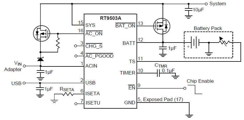
Figure 7. Typical application circuit of the RT9503A.
However, when the battery temperature is too high or too low, charging and discharging can still be permitted as long as the unique Li-ion battery properties are taken care of. For example, Japan Electronics and Information Technology Industries Association (JEITA) standard requires to lower the maximum charge current and charge voltage when battery temperature is too low or too high. The diagram shown below is from the datasheet of the RT9519A, which is a battery charger solution for JEITA compliance.
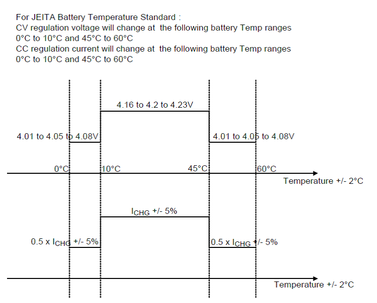
Figure 8. Battery charger solution for JEITA compliance.
For this reason, the RT9515 provides two pins, VSET and ISET, so that it can switch between two different charge voltages and currents, respectively. The following diagram illustrates their corresponding relationships. After the system detects the actual battery temperature, it can choose the desired charge specifications by setting VSET/ISET to the appropriate values accordingly.
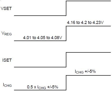
Figure 9.
RT9528 has the built-in temperature measurement function, implemented by the characteristic of some specific-model thermistor. The application circuit diagram can be seen below.
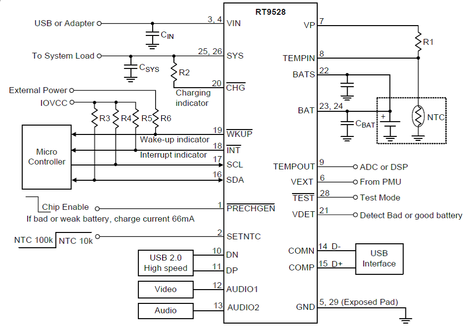
Figure 10. RT9528 application circuit.
The RT9528 provides a 3.3V regulated voltage to R1 and a thermistor NTC through the VP pin. The voltage sensed at TEMPIN reflects the resistance of the thermistor NTC, because the NTC resistance is the function of temperature.
The RT9528 supports an option between two different NTC models: NCP15WF104F03RC and NCP15XH103F03RC. The SETNTC pin should be set at HIGH/LOW values to choose between these two models.
With the internal register settings, the RT9528 can determine the temperature range of the battery: too hot, hot, cold, or too cold. It can then program when to switch charge current/voltage, or to inhibit battery charging based on the properties of different batteries. Refer to the RT9528 datasheet for further details.
The following two diagrams illustrates how charge current of the RT9528 changes when battery temperature changes from normal to cold, and how charge voltage changes from normal temperature to hot, where VTS variations represent temperature variations.
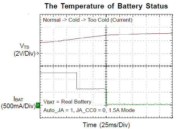
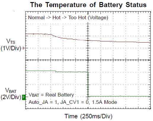
Figure 11.
Some other ICs can change charge currents/voltages by external control circuits or take commands from the communication interface. For example, The RT9450A, the RT9451 and the RT9480 are all with such communication capability. General-purpose wide-input-voltage charge ICs, such as the RT9531, the RT9535 and the RT9538, only provide the most basic output functions of constant currents and constant voltages, and leave all the design settings to the hardware designers. They are undoubtedly a big help in terms of building up a comprehensive battery management system. In fact, these products can be used in stand-alone battery management systems - mobile power supplies, which is exactly what the RT9480 is purposely developed for. It has integrated all the common power management functions for mobile power supplies into a single chip. All the functions and performances can be preset. Once the setup is done, it can be used off-line and there is no need to make adjustment. The manufactured RT9480s have been preset with the most general uses and its datasheet is also subject to be written in this setting. The RT9451 can support charge current as high as 4A. The charge current and charge voltage can be set arbitrarily within a wide range, which makes the RT9451 widely used in many battery applications. The RT9451 not only supports high charge current, but also supports USB-OTG applications. The output voltages can also be set, and the output currents can be as high as 1.6A. This makes the RT9451 an incredible choice for USB-OTG applications.
Charge Timer
A normally-designed Li-ion battery charge management system can fully charge a battery within the normal charge time. However, if some accidents occur, such as that the battery leakage exceeds the limit or that a load is connected to the system (especially connected in series), the charge termination condition may never be reached. In this case, a charge safety timer is a must-have configuration to set a maximum charge time. Once the charge duration exceeds the time limit, no matter what stage the battery is at, charging will be automatically terminated. Charging can be resumed only when the system is reset.
Not all chargers have a safety timer built in. However, each device with a safety timer may have its own way to implement the timer based on the design.
As below, there is an internal constant current source and a controllable discharge path, connected to the TIMER Pin of the RT9525. With an external capacitor, it makes a time constant. The internal counter will count the times of the charge and discharge operation to a predetermined value, and then it will shut down the charge circuit. By changing the capacitance, the maximum charge time can be changed.
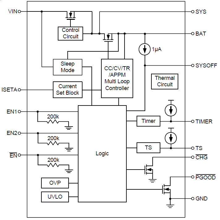
Figure 12. Functional block diagram of RT9525.
The RT9451 has two safety timers, 32-min and 32-second, for charge mode and boost mode, respectively. MCU must access the RT9451 via I2C interface before the timer expires and the timer will be reset after the access. If MCU does not reset the timer by the access, once the timer expires, the RT9451 will terminate the present job and enter the high impedance mode to ensure safety. The following diagram shows when MCU does not access the RT9451, and does not reset the timer, as the timer expires, the output will be automatically shut down. Note that VIN is the output in the boost mode.
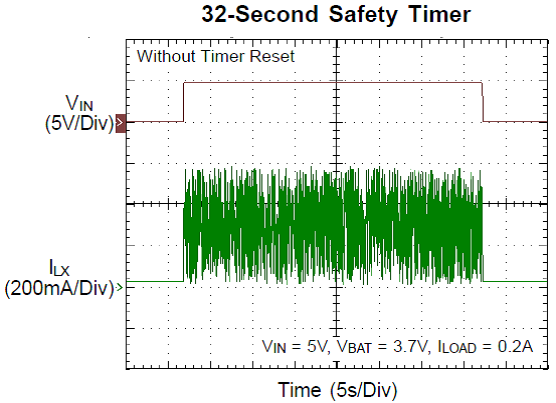
Figure 13. Performance of RT9451's internal 32-second safety timer.
The following diagram, from the RT9451 datasheet, illustrates the relationship of the RT9451 internal safety timer and other operations.
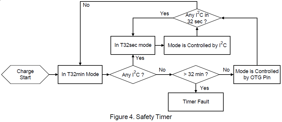
Figure 14. Relationship of the RT9451 internal safety timer and other operations.
Power Path Management
Charge management devices with no power path management function are simpler. Their charge circuits are like the RT9526 application circuit shown below.
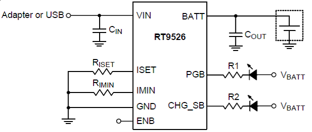
Figure 15. RT9526 application circuit.
The load of such a system is usually connected to batteries in parallel. This kind of connection is often called serial connection. However, the way that an external power supply directly powers the load is called parallel connection. The application circuit of the RT9503A, mentioned previously, is a typical parallel connection. When connected with an external power supply, the battery will be charged by the current through the internal path of the IC, and this charge current also flows serially to the load via externally connected diodes and MOSFETs.
Circuits in serial connection are simple and low-cost, as long as the electrical energy in the battery is sufficient to power the load. The drawback is that once the battery cannot afford the need of the load, the load cannot enter the operation mode immediately even when the power is plugged in. For example, when the battery of a cellular phone is completely drained, and is plugged into the charger, there is a period of time that the cellular phone cannot be turned on. Only when the battery is charged up to a certain level, the system can start working because most of the loads require 3.3V as operating voltage. When the battery voltage is too low, it cannot supply 3.3V output voltage for the load. Therefore, the system cannot be powered on until the battery voltage rises to the certain level.
To make the system work in the whole range of the battery voltage requires automatic Buck-Boost converters, like the RT6150 series, which will be introduced sometime later.
On the contrary, the parallel-connection system can still work because it does not care what powers the system. The RT9503A application is one of the examples. However, the drawback is that when the external power supply plugs in or unplugs, the supply voltage may have a great spike, which can be a tough challenge to regulators in the system load. Besides, a large spike may appear at the output, which is unacceptable to some systems.
Devices with auto power path management can accommodate all the requirements, such as input limitation, system requirement and battery charge. The RT9519A is a device equipped with auto power path management function as well as other functions, such as JEITA compliant, mentioned previously. The RT9525 is simplified in its functionality, and below is the RT9525 application circuit.

Figure 16. RT9525 application circuit.
The VIN pin is connected to 5V power supply, from AC power adapter or USB, and the BAT pin is to the battery. The TS pin is connected to a thermistor, which is used to determine under what temperature that the battery is not allowed to charge. The resistor RISETA is for charge current setting and CTIMER for the maximum charge time. The SYS pin is where the load is connected. The state of the SYSOFF pin decides whether the battery should supply the load or not. The EN pin is to enable the IC, and the EN1/2 pins are used to set VIN input current limit. The corresponding settings are shown in the table below.
Table 1. Input current limit setting table
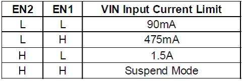
The feature of input current limit is useful in adapting to various power supplies, which is especially necessary for the USB interface.
When the input current is limited, how to allocate the limited input current between the battery and the load? When the input current cannot supply enough for the load, how to supplement it with the battery? This is the problem that path management needs to solve. See the RT9525 functional block diagram.
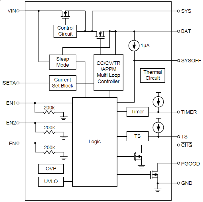
Figure 17. Function block of RT9525.
The two MOSFETs, connecting the VIN, BAT, and SYS pins, make the desired management path. The currents, voltages, and the relationship among these three pins are clearly presented in the datasheet.
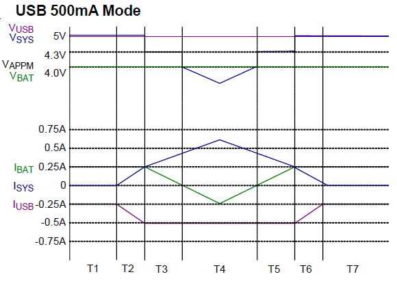
Fgure 18.
The above diagram illustrates the behaviors under USB 500mA mode, that is, when input current limit is 500mA. The data will be different under other input current limits, but the performance will be similar. According to the different current and voltage variations, the operation is divided into seven conditions and they are identified as T1~T7, respectively. Seven conditions with different current and voltage variations at the pins are organized in the following table:
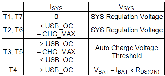
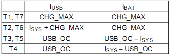
Path management system will first direct the power to the system load. If the input current cannot supply enough power to the load, the battery will supplement the current for the load. However, if the power consumption of the load drops down, the excess power from the external power supply will be directed to charge the battery.
USB Interface Specifications, Limitations and Identifications
When a USB device connected to a host, the USB specification only allows a maximum current of 100mA drawn from the power bus, VBUS, of the USB host before the device is identified. After the device is identified, it may draw a maximum current of 500mA. The two modes, USB100 and USB500, of the RT9525 are designed for this specification. Under these two modes, the RT9525 can actually draw 90mA and 475mA at most, respectively.
The new USB specification increases input current limit rating, but still keep it. The load-driving capability of the power adapter, which draws power directly from power grids, can be considered with no current limit. Early charge ICs, as the RT9502 and the RT9503A, dealt with different power sources separately, whether the power is from USB or adapters. However, if there is only one input power pin for some charge ICs, how can they identify where exactly the 5V input power is from?
The specification of the cellular phone chargers in China, established a few years ago, describes as using USB ports as a physical structure, and USB data pins, D+ and D-, for data exchange. When these two pins are short-circuited, it indicates the power input is from a power adapter. This is different from the standard USB signal pins. Since USB is used for exchanging data, the two pins are internally connected to the input and output of the operational amplifier, which are all in high impedance. It is not possible to identify that the two pins are short. Consequently, if injecting a current through either pin and receiving the current at the other pin, then these two pins are considered short-circuited and this is how the AC adapter is identified. Vice versa, it is identified as a USB port. This is how the USB port detection is implemented in the RT9451, which supports USB-OTG applications. However, please note not all charge ICs have such feature. Most of them do not, including the products of Richtek.
If the charger IC has no such feature of USB detection, it can only count on other approaches to find out. It is not difficult for the systems with USB communication functions.
Over-Voltage and Over-Current Protections at the Pins
For almost all the applications with charge management devices, these devices are usually located at the interface of the systems, where external cables plugged and unplugged repeatedly, and the currents passing through on and off. Although most external power supplies are 5V, the actual voltages appearing at the interface could be greatly varying. Sometimes, it is inevitable that the voltages are higher than the ICs’ voltage rating. To avoid the system damages, due to high input voltages, most of the Richtek’s 5V charge management devices have overvoltage shutdown protection and the capability to withstand high input voltages up to 28V. The former is to protect the systems from being damaged by high voltages. (For most of the systems, the overvoltage protection threshold is set at 6V.) The latter is to assure that a charge management devices will not be damaged due to intolerance of high voltages.
For charge management devices with low input voltage rating, over-current and over-voltage protectors must be added externally. The RT9718, an integrated protection device, is a good choice, for it integrates over-temperature, over-current, input over-voltage, and battery over-voltage protections in one chip. When any of the above events occurs, it will disconnect external power from the system in a certain period of time to ensure the safety of the system. Since it can tolerate high input voltages, as 28V, it will not be damaged easily.
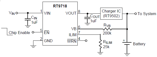
Figure 19. RT9718 application circuit
The above diagram illustrates the RT9718 application circuit. The over current protection threshold, that is the maximum current allowed, can be set by RILIM, whichis connected between the ILIM pin and GND. Over voltage protection threshold voltages are already specified in model numbers. The four models represent four over voltage thresholds, respectively.
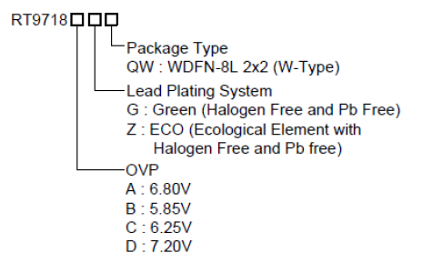
Figure 20. RT9718 ordering information
When an over-voltage event occurs, the RT9718 will turn off the output path quite soon, within at most 1μs, to prevent the following circuits from any further damage due to the high voltages. When input voltage drops back below the OVP threshold by 100mv, lasting for 8ms and with everything back to normal, the switch will be reopened to provide the power for the following circuits.
As to over current protection, the RT9718 has a delay response time of 180 μs. This is to prevent overreacting. After all, only a sustaining over current situation is what is concerned. The recovery delay for over current protection is 64ms, and when the OCP happens for consecutive 16 times, the internal MOSFET switch will be turned off permanently unless POR reoccurs. The RT9718 monitors the battery over-voltage condition via the VB pin. The battery OVP threshold is 4.35V. When an OVP event happens, it has to last for more than 180μs. After each POR, OVP can only happen for consecutive 16 times, and then the MOSFET switch will be permanently turned off. The resistor RVB can affect the OVP threshold and leakage current through the VB pin. If RVB is greater, the OVP threshold error is larger. However, if RVB is smaller, the pin leakage current increases. Therefore, it is important to get a trade-off when choosing the appropriate RVB. The suggested resistance for RVB is between 200 kΩ ~ 1MΩ.
Over Temperature Protection (OTP) does not monitor the temperature outside of the ICs. If the internal temperature reaches 140℃, the output path will be turned off. The IC will resume the operation only until the internal temperature drops by 20°C.
Other than OTP, any protection event will make the WRN pin to pull LOW. It can help system designers to understand and solve the problems.
Linear Charger and Switch-Mode Charger
Under any circumstances, only when the external power supply voltage is higher than the battery voltage, the current can flow to charge the battery. Therefore, the output voltages of almost all power adapters for charging are higher than the highest battery voltages. However, external power supplies cannot charge batteries directly, because the current may be uncontrollable. And this is why charge management devices are necessary.
The easiest way to implement a circuit to control the constant-current, or constant-voltage source between the external power supply and the battery is to use a linear adjustable constant-current, or constant-voltage source. This is why linear charge management devices are so common. The following diagram illustrates how the RT9526 functions:
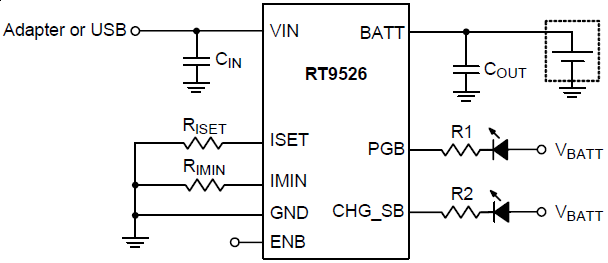
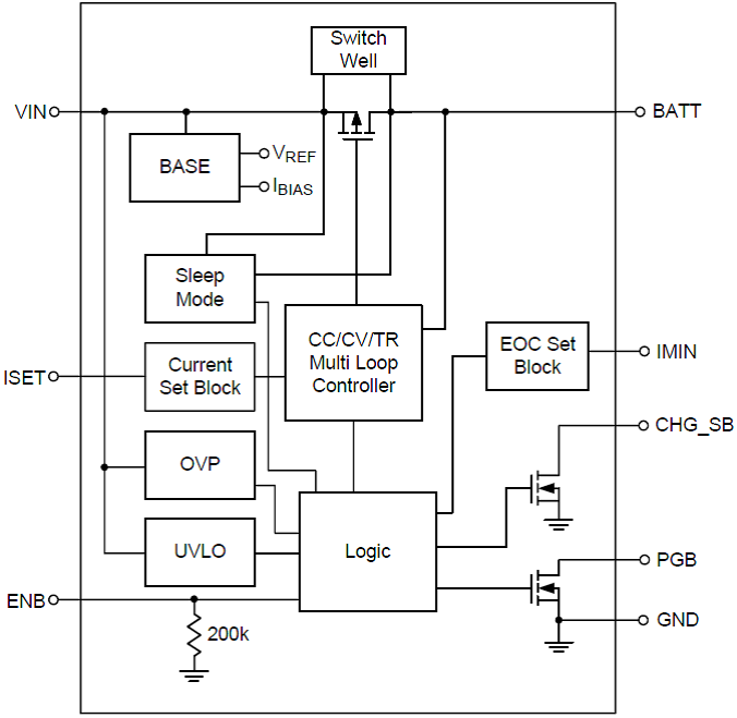
Figure 21. The RT9526 application circuit for a linear charger and the functional block diagram
A MOSFET, between the pins, VIN and BATT, is the control device between the external power supply and the battery. Turning this pass transistor ON/OFF can control the constant-current and constant-voltage source, which is indeed a constant voltage source with adjustable current limits.
Due to the voltage difference between the input and the output and the current through the pass transistor, it consumes power and is lost to heat. This is a power loss and can be disastrous especially when the battery voltage is low and the input supply is high. To minimize such power dissipation, the input voltage and the charge current must be lowered. However, it may bring some other issues, or it may even fail.
Switch-mode converters can resolve the issue, mentioned above, because buck converters are one of the best. The RT9451, using buck converters, provides a 4A charge current and 12V as highest operating voltage, which makes the RT9451 an incredible device for a linear charger. For a low charge current of 1.5A, and 5V input voltage, the RT9450A could be a better choice.
The RT9531/RT9535/RT9538 series are also battery chargers with buck structure. The operating voltage can be as high as 28V, and the load voltage 25V. Combining with various control schemes, they can charge all kinds of rechargeable batteries.
Under the condition of the limited input current, a DC/DC system can be considered a constant-power charger. In some sense, a buck-mode charger is like a current amplifier so its charge rate can be higher than that of a linear charger. This feature is of great significance as the battery capacities keep rising these days.
The following diagram provides a comparison of a linear charger and a switch-mode charger with charge current and charge time under USB500 current limit mode, given that they charge the same battery. From the diagram, it takes a linear charger 14000+ seconds for the current to drop to 100mA; however, a switch-mod charger 12500 seconds only.

Figure 22. Comparison of linear charger and switching charger with charge current and charge time under USB500 current limit mode.
Contrary to the control circuit of a linear charger, consisting of only a MOSFET, a switch-mode charging circuit is much more complicated. The basic building block is shown as below:
Practically, it is a buck regulator which provides the output with constant current and constant voltage. Because the main body of a synchronous buck regulator is reversible, with only a modification, it can be transformed as a boost circuit. However, this boost circuit can only provide the boosted battery voltage to the Vin pin, which in turn powers the external devices. This is exactly what USB-OTG applications would need. The buck-mode RT9450A and RT9451 are designed with this feature.
The Detection and Adaption of Power Adapters
Early charge management devices do not care whether the power adapters, which power them, are good or bad. As long as the input voltage exceeds the POR (Power ON Reset, power-on reset) voltage, the device will enter the operation mode and start charging a battery according to the predetermined charge strategy. Just to make sure that the input voltage does not exceed the maximum rating of the ICs.
Since over voltages, through a linear charger, may cause heat problems or damage the subsequent circuits, over voltage protection is so important that it is the first function to be included in charge ICs.
Sometimes, when the power supplied by a power adapter is insufficient, a large load current will pull the adapter output voltage down. However, as long as the adapter voltage is higher than the battery voltage, a linear charger can still charge the battery. If the voltage difference is not enough, the charge current will decrease. During the process, the balance can automatically appear as long as the ICs can be made operable at lower voltages to adapt to such a situation.
The following is the introduction to a few new methods in a conceptual way, combined with the corresponding to product examples. The datasheets can be very helpful in understanding the applications of the relevant technologies.
AICR
AICR is the abbreviation for Active Input Current Regulation. Charge current, but not input current, is the major concern for a charger. However, for a linear charger, charge current is basically input current and the excess part is consumed by the device itself, which is relatively small. For a charger with path management function, or a switch-mode charger, input current is usually not equal to charge current. In this case, input current becomes a concern, which. USB100 mode and USB500 mode are defined for.
MIVR
MIVR is the abbreviation for Minimum Input Voltage Regulation.
Since the current supply capability of any actual voltage source is limited, when it cannot afford the current demand, the output voltage will decrease. This may cause some problems: output power drops (not all power supplies are like this); UVP (under voltage protection) event of the power supply occurs; the power supply breakdowns or repeatedly restarts; the lowest operating voltage is lower than the load voltage such that the load cannot operate normally. All these problems will be even serious if the system is USB-powered, because the host may be down and will bring catastrophic consequences.
MIVR function is to prevent input voltage from dropping below the minimum voltage. Since the decrease of the input voltage is due to over current, the solution is to lower the current. This is how The RT9451 does. It sets the minimum input voltage level from 4.2V to 4.76V in a step of 80mv. The following figure shows how the RT9451 adjusts the current. Due to insufficient current provided by the adapter or USB input, the expected charge current can never be reached, so the minimum input voltage is only be at the predetermined voltage level.
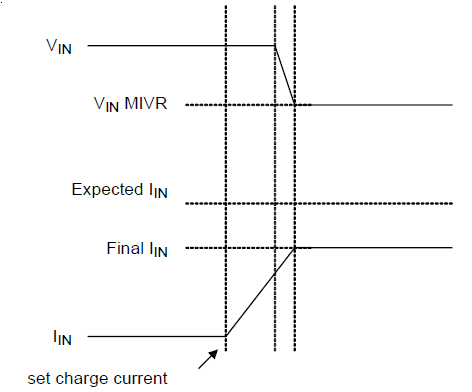
Figure 23. RT9451 minimum input voltage adjustment.
Bad Adapter Detection
Bad adapter detection is used to detect the power capability of the power adapter. This detection will only be executed when the input voltage of the charger rises as during power on. When the RT9451 detects VIN has risen above VIN(MIN), an internal current sink of 30mA, connected to the VIN pin, will be turned on. If during this period of time, the current sink is still on and lasts for 30ms, and VIN is still above VIN(MIN), then the detection passes, and the subsequent operations can continue. Otherwise, the RT9451 will stop all the operations, and set CHBADI. The MCU in the system can use the state information to continue the further operations correspondingly. If VIN is below VIN(MIN), the bad adapter condition occurs. The RT9451 will repeat the detection process every 2s until the condition is removed. The following diagram, from the RT9451 datasheet, shows the detection procedure and the flowchart.
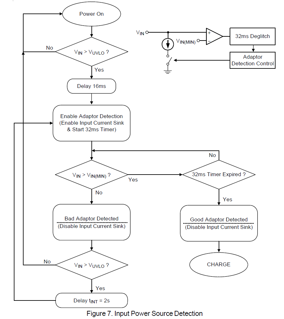
Figure 24. Detection procedure and the flowchart of RT9451.
Status Indication
HMI (human-machine interface) is the interface for users to understand system status, and to control devices, where status indication is the most basic function.
When charging Li-ion/polymer batteries, whether the power supply functions normally, or whether charging is still on-going, etc., is what end users are concerned about. Each Richtek battery charger model provides such information, usually in the forms of states of some pins or the data stored in the internal registers. The information can be expressed by external LEDs, or read into the system controller and expressed in other ways so that the users can have better understanding of the present situation and can have the better usage of the batteries. The LED symbols in many of the previous diagrams illustrate their role. Note that the output pins of the ICs are expressed in either 2 states, as ON/OFF, or 3 states, as ON/OFF and high-impedance, which the designers can be aware of and make good use of.
The Measurement of the Battery capacity and its Solutions
Simple status indication can enhance the comfort level of end users, but it is only to the lowest degree. With only the simple state information, it is not quite possible to know how full the battery is or to predict how the process goes in advance. For example, it would not tell how long the battery can be fully charged or how long the battery would last under a certain state. The battery capacity measurement tool - Battery Fuel Gauge (Battery Gauge) – is what is needed to solve these problems. Here is the application circuit of the RT9428:
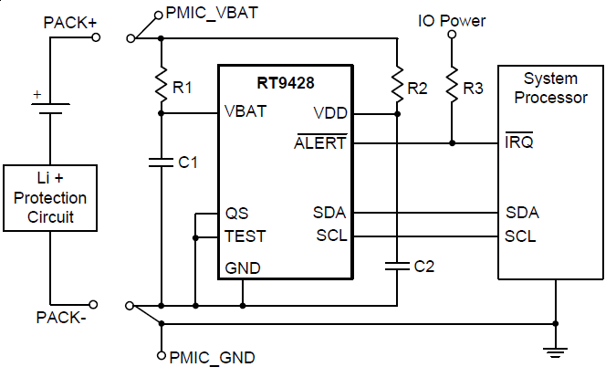
Figure 25. RT9428 application circuit
In the datasheet, the RT9428 is described as “system-side fuel gauging”, for it is not placed in a battery pack. This is different from the way how notebook computers use battery gauges. If one battery cell is replaced, the capacity information the RT9428 sends out is of the new battery. That means the RT9428 can sense the immediate capacity of the battery, which is connected to it. The RT9428 calculates the battery capacity by the voltaic gauge algorithm, which is based on the battery voltage.
Take one actual cellular phone as an example. The curve below shows the measured battery voltage versus the time elapsed during discharge.
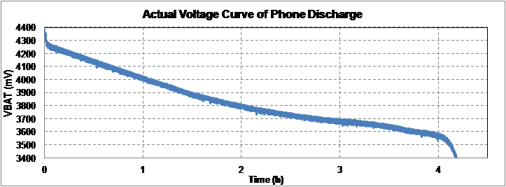
Figure 26. Battery voltage v.s the time elapsed during discharge
Correspondingly, the relationship between battery voltage and state of charge can be obtained as shown below.
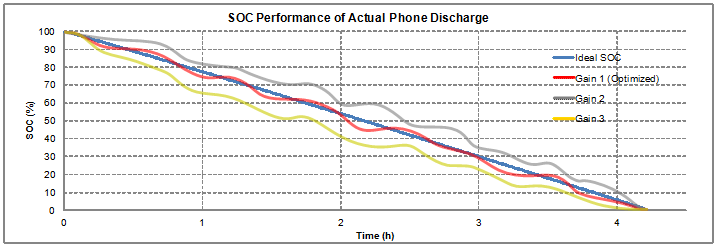
Figure 27. SOC performance of actual phone discharge
The blue straight line in the previous diagram indicates the ideal battery state of charge. As long as the battery voltage is measured, the ideal battery state of charge can be obtained. Unfortunately, the actual battery charge-discharge curve is not ideal at all. Due to the internal resistance of the battery and the constantly changing load current, the actual measured battery voltage and the actual battery voltage are always different. Therefore, the accurate battery state of charge cannot be obtained from the measured battery voltage. The yellow and the blue curves depict the measured data, which are not acceptable due to the large errors. The measured data need to be optimized to be like the red curve, which is regarded as acceptable. How to make the measured data usable by optimizing the curve completely relies on the thorough understanding of the battery characteristics.
To realize what is mentioned above, the users who choose the RT9428 as the battery gauge have to feedback the battery-related measurement data to Richtek, or provide the batteries for Richtek to measure the data. After the measured data being analyzed and investigated, the characteristic values can be obtained. The values will be entered into the users’ system drivers. When the system is at work, it will provide the temperature data and the characteristic values to the RT9428 in real time via I2C bus. The RT9428 will use the information and the battery voltages, which the RT9428 continues receiving, to calculate the state of charge with many iterations and feedback the information to the system. The corrected data can better reflect the actual state of charge of the battery. The two diagrams below show the relationship between the calculated and the actual battery state of charge under different charge/discharge conditions. The largest errors are within +/-3%, which is much better performance than other manufacturers.
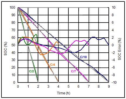
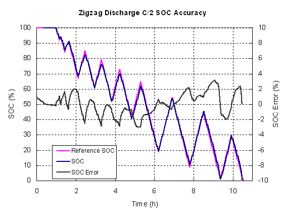
Figure 28. Relationship between the calculated and the actual battery state of charge under different charge/discharge conditions
The Test Mode of Chargers
Can the system function normally if the system is not connected to a battery, but is connected to a power adapter? This could be a problem to many charge management devices.
Because the mismatch between the load characteristics and the charger, the charger can enter the pre-charge state or charge termination state easily. Under either situation, the load cannot be powered normally. Therefore various situations can happen.
To solve this, under the test mode, the charger will set the state of the pin, connected to the load, as a constant voltage output. Henceforth, it can be a stable power supply.
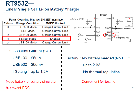
Figure 29. Test Mode of RT9532
Take the previous diagram as an example. Users can apply pulse signals at the pin EN/SET to change operation modes, including USB100 mode, USB500 mode, ISET mode (the maximum charge current, 1.2A, can be determined by RISET), and factory mode. The factory mode is used as a test mode. Under this mode, the system can operate normally with no battery plugged in. And the device can provide the output current as high as 2.3A for the system without entering charge termination state.
The approach that the RT9532 uses, a series of pulses entering at one pin to change the operation modes, is relatively simple and cost reduced. Compared with others with many pins, the RT9532 has fewer pins. Compared with others using I2C bus, the internal circuit of the RT9532 is much simpler. If only switching among 4 modes, the advantage is not that obvious. But if switching among more modes, this advantage stands out. The following diagram is a real case of the RT9532, which adds no new pins but instead adds the function of adjusting charge voltages. This approach can be considered as time for space.