Comparing Buck Converter Topologies
Abstract
This report describes three DC/DC buck converter topologies: Current Mode, Current Mode-Constant On Time and Richtek Advanced Constant On time topologies. The differences between the three topologies are explained and the advantages and disadvantages of each type are listed with respect to the end application.
1. Introduction
This report describes three DC/DC buck converter topologies: Current Mode, Current Mode-Constant On Time and Richtek Advanced Constant On time topologies. The differences between the three topologies are explained and the advantages and disadvantages of each type are listed with respect to the end application.
2. Current Mode Buck Converters
The block diagram of a current Mode buck converter is shown in Figure 1.
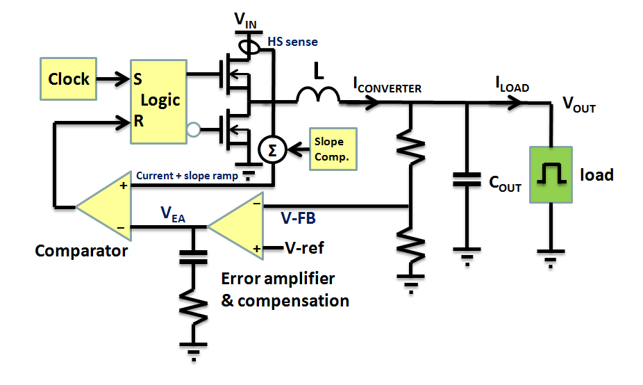
Figure 1. Current Mode Block Diagram
In the classic current mode control, a fixed frequency clock activates the upper MOSFET. An error amplifier looks at the difference between the feedback signal and reference voltage. The rising slope of the inductor current is compared with the output of the error amplifier and when the inductor current exceeds the error amplifier voltage, the upper MOSFET is switched off. The inductor current then flows via the lower MOSFET and the system waits for the next clock pulse. A slope compensation ramp is added to the current ramp to avoid sub-harmonic oscillation at high duty-cycles and improve noise performance. In current mode converters, the loop bandwidth (FBW) is set by the compensation components at the error amplifier output and is limited to much less than the converter switching frequency. The waveforms for Current Mode steady-state and load transient operation are shown in Figure 2.
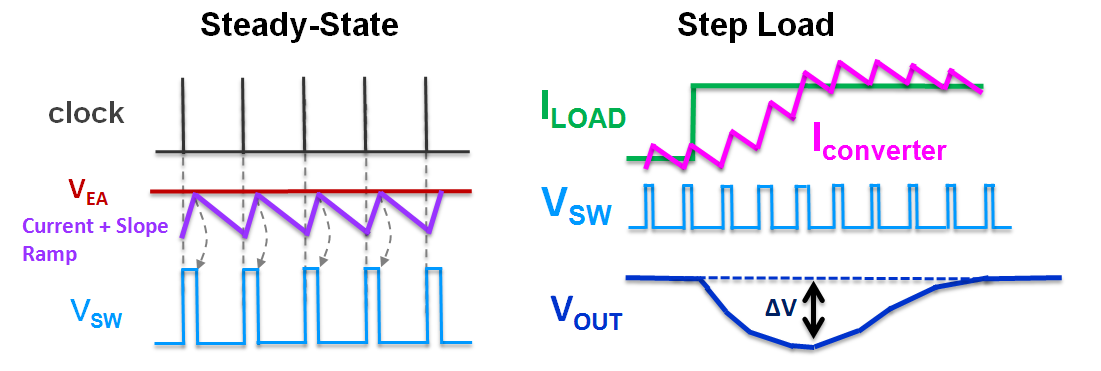
Figure 2. Current Mode Steady State and Load Transient Waveforms
The fixed clock makes current mode control systems relatively slow to respond to sudden load changes, especially in low duty-cycle applications, since once the upper MOSFET has been switched off, it remains off until the next clock cycle. The limited bandwidth also limits the available duty-cycle that can be achieved when the converter is trying to meet new load demands. In applications that exhibit fast load steps, current mode converters will show relatively large output voltage fluctuation. The voltage sag ΔV during a step-load is related to load step amplitude and speed, output capacitance and converter bandwidth. To ensure good stability in current mode converters, the bandwidth is usually set at 1/10 of the switching frequency or less.
Another drawback of current mode converters is that the decision point for controlling the switching of the MOSFETs is made during the ON time of the upper MOSFET, where current level and system noise are high. Noise filtering is needed and this results in certain limitations with respect to the minimum ON time of the upper MOSFET, which in turn limits the minimum duty-cycle range of the buck converter. The fixed slope compensation normally also poses a limit on the inductor values that can be used at certain input and output voltage conditions.
Current mode converters also have advantages: the internal clock keeps the switching frequency very stable, regardless of the input and output conditions, which in some applications can be an advantage. The internal clock can also be synchronized to external clock signals, making it possible to run several converters on the same frequency.
Table 1 lists the advantages and disadvantages of the Current Mode buck converter.
Table 1
|
Current Mode Buck Converter
|
|
Advantages
|
Disadvantages
|
- Stable fixed
frequency
- Can be
Synchronized to ext. clock
- Established
technology
- Stable with
MLCC
|
- Slow response
to fast load steps
- Needs error amplifier
compensation
- Needs slope
compensation
|
3. Richtek Current Mode-COT (CMCOT) Buck Converters
The block diagram of a Richtek Current Mode COT converter is shown in Figure 3.
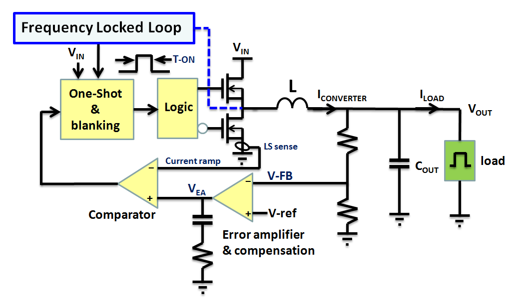
Figure 3. Current Mode-Cot Converter Block Diagram
CMCOT buck converters do not have an internal clock; the upper MOSFET always conducts for a pre-defined fixed ON time. The duty-cycle is regulated by changing the OFF time of the upper MOSFET. CMCOT converters also contain a current sense and error amplifier, but now the falling slope of the current is compared to the output of the error amplifier. Current is therefore sensed in the lower MOSFET which is much easier to do and less prone to noise pick-up, especially in low duty-cycle conditions. The fact that the system does not need to wait for a next clock-cycle makes it possible to react more quickly to sudden step loads; as soon as the output voltage drops and the error amplifier voltage rises above the falling current slope, a new ON time is triggered and converter current rises again. The waveforms for CMCOT steady-state and load transient operation are shown in Figure 4.
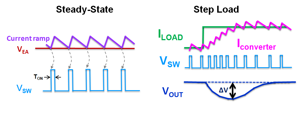
Figure 4. Current Mode-Cot Steady State and Load Transient Waveforms
The current valley must follow the error amplifier output, so gain and speed of the error amplifier affect the control speed. In the CMCOT topology, the maximum bandwidth that can be set by the compensation is related to the inverse of the ON time rather than the switching frequency as in current mode. So CMCOT converters can have higher bandwidth than current mode converters and show less output voltage fluctuations during fast load steps. CMCOT does not suffer from sub harmonic oscillation at high duty-cycles, and therefore does not need slope compensation, which allows a wider choice of inductor values.
In a pure fixed ON time topology, switching frequency would deviate considerably at different input and output voltage conditions. In Richtek CMCOT, the ON time is controlled by a special circuit that slowly adjusts the ON time to regulate the average switching frequency to a defined value. Similar to current mode, is the voltage sag ΔV during a step-load is related to load step amplitude and speed, output capacitance and converter bandwidth, with the difference that in CMCOT the compensation components can be set for a bandwidth higher than 1/10 of the switching frequency.
CMCOT also has some disadvantages: Since the converter controls frequency to regulate the output voltage, this makes it impossible to synchronize the converter to an external clock. The frequency control loop also means that the switching frequency can show some variation during load transients.
Table 2 lists the advantages and disadvantages of the CMCOT buck converter.
Table 2
|
Richtek Current Mode-COT (CMCOT) Buck Converter
|
|
Advantages
|
Disadvantages
|
- Fast response
to load steps
- Low Side
current sense
- Small minimum
ON time allows small duty-cycles.
- Constant
average frequency
- Stable with
MLCC
- Does not need
slope compensation
|
- Needs error
amplifier compensation
- Cannot be
Synchronized to ext. clock
- Some frequency
deviation during load transients.
|
4. Richtek Advanced-COT (ACOT®) Buck Converters
The block diagram of a Richtek ACOT converter is shown in Figure 5.
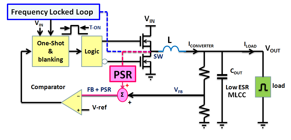
Figure 5. ACOT Block Diagram
ACOT converters do not contain an error amplifier or current sense; they directly compare the feedback signal (DC level + ripple voltage) with an internal reference. When the feedback signal falls below the reference, a new fixed ON time is generated and inductor current rises. If the output voltage has not recovered, another ON time is generated after a short blanking period until the inductor current matches the load current and output voltage is at its nominal level again. Conventional COT converters need some output voltage ripple, in phase with inductor current, to switch in a stable manner. This requires output capacitors with some ESR.
To be able to work with low ESR ceramic capacitors, Richtek Advanced-COT topology makes use of an internally generated PSR ramp signal, which is added to the ripple and the DC level from the converter output. These are summed and then compared with an internal reference. When this voltage sum drops below the reference, the comparator triggers the ON time generator. A sudden drop in output voltage will immediately result in a new ON time, and the converter can generate successive ON times as long as the output voltage has not recovered. This makes the ACOT topology reaction speed to load transients extremely fast. A special frequency locked loop system will slowly adjust the ON time to regulate the average switching frequency to a defined value.
The waveforms for ACOT steady-state and load transient operation are shown in Figure 6.
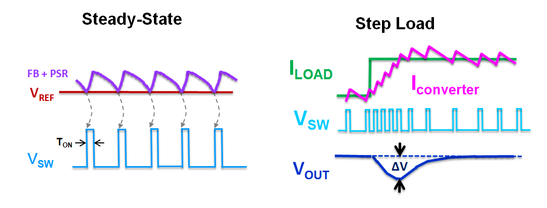
Figure 6. ACOT Steady-State and Load Transient Waveforms
An approximate formula for ACOT converter voltage sag during load transients is shown below:
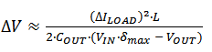
where δmax is the maximum duty-cycle that the converter can generate during a load transient, related to ON time and blanking time.
ACOT converters can exhibit large frequency deviations during fast load transients. When the end application is sensitive to certain switching frequency bands, this sensitivity should be checked with the ACOT converter in dynamic load condition, where the dynamic frequency swing is most pronounced.
Table 3 lists the advantages and disadvantages of the ACOT buck converter.
Table 3
|
Richtek Advanced-COT (ACOT®) Buck converter
|
|
Advantages
|
Disadvantages
|
- Extremely fast
response to load steps
- Does not need current
sense
- Small minimum
ON time allows small duty-cycles.
- Constant
average frequency
- Stable with
MLCC
- Does not need
slope compensation
|
- Cannot be
Synchronized to ext. clock
- Large FSW
deviation during dynamic load
|
5. Comparison Measurements
The actual behavior of the three topologies was compared by using 3 Richtek low voltage Buck converters in a 5V→1.2V/1A application:
- RT8059
(1.5MHz/1A Current Mode buck converter)
- RT8096A
(1.5MHz/1A CMCOT buck converter)
- RT5784A
(1.5MHz/2A ACOT buck converter)
Key components (output capacitors and inductor value) in all three applications were identical, so the measurement results and differences are purely caused by the different control topologies, and can be directly compared.
The converters were tested on fast load steps (dI/dt rates similar as seen in MCU core and DDR loads.
RT8059 application and test results:
Figure 7 shows the application with Current Mode buck RT8059, which has internal compensation. An external feed-forward capacitor C7 was added to optimize the response.
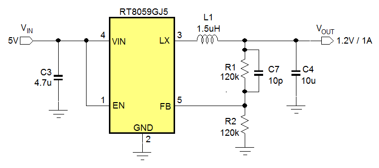
Figure 7. RT8059 5V→1.2V/1A Application
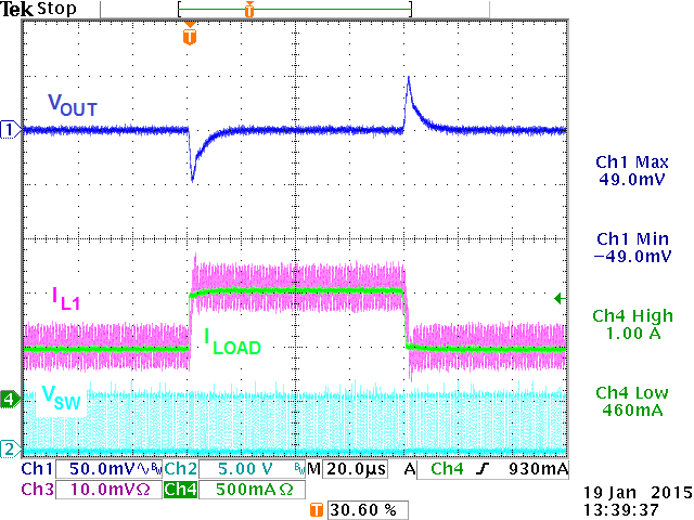
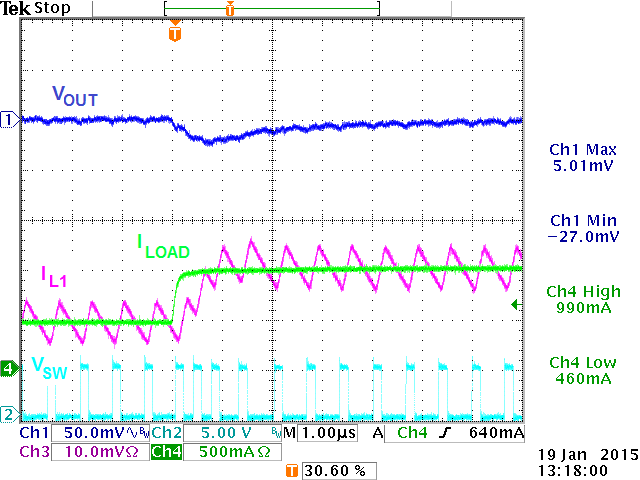
Measurement results: (Current Mode)
|
RT8059 with 550mA fast step load
|
Detail of step load
|
|
|
|
|
Output voltage sag is 65mV or 5%.
|
Duty-cycle changes gradually during transient.
|
Figure 8
RT8096A application and test results:
Figure 9 shows the application with CMCOT buck RT8096A, which also has internal compensation. An external feed-forward capacitor C2 was added to optimize the response.
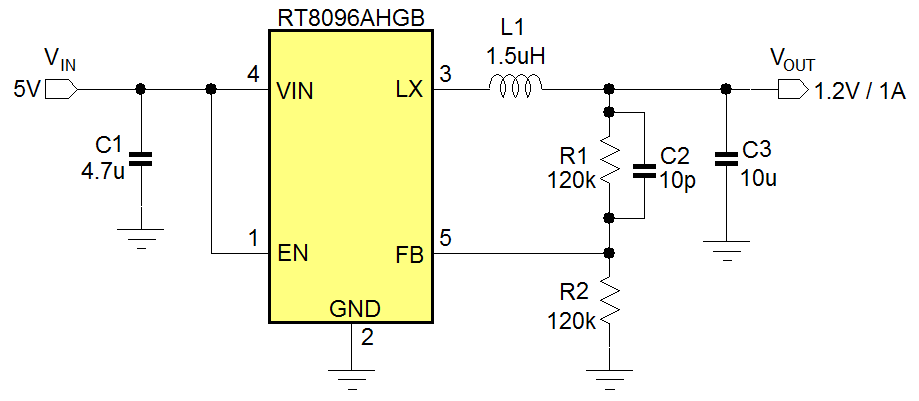
Figure 9. RT8096A 5V→1.2V/1A Application
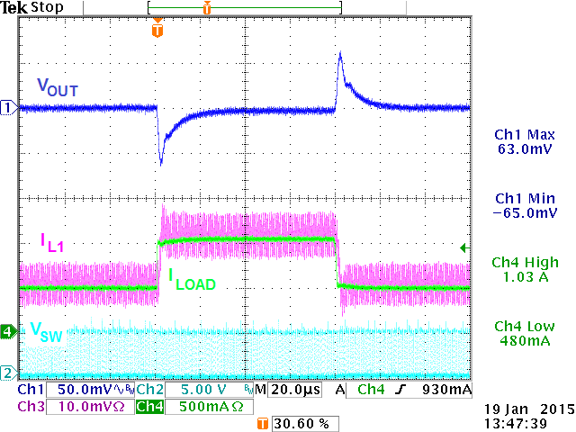
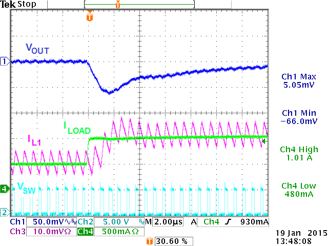
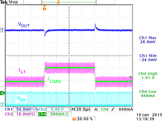
Measurement results: (CMCOT)
|
RT8096A with 550mA fast step load
|
Detail of step load
|
|
|
|
|
Output voltage sag is 49mV or 4%.
|
Frequency will increase during transient, thereby increasing duty-cycle.
|
Figure 10
The measurements show that in this 5V→1.2V application, CMCOT buck has around 20% better step load response compared to CM buck, so in this case the difference is not so big. CMCOT applications with higher step-down ratios will have smaller on times and therefore can have higher bandwidth, so those applications will show bigger differences in step load response.
RT5785A application and test results:
Figure 11 shows the application with ACOT buck RT5785A , which has a direct VOUT connection to determine ON time. No feed-forward or other compensation is needed.
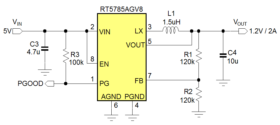
Figure 11: RT5785A 5V→1.2V/1A Application
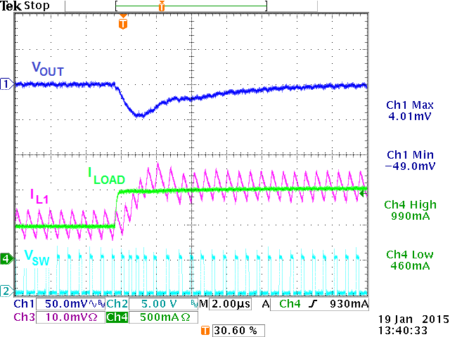
Measurement results: (ACOT)
|
RT5785A with 550mA fast step load
|
Detail of step load
|
|
|
|
|
Output voltage sag is 24mV or 2%.
|
Frequency will immediately increase to obtain maximum duty-cycle during transient.
|
Figure 12
The ACOT buck has the superior step load response of all three control topologies.
6. Summary
When choosing a buck converter for your application you need to consider which parameters are most important for the end application. If the system is susceptible to noise at certain frequencies, you also may want to use a current mode buck converter, and maybe synchronize it to an external clock signal to set the switching frequency very precisely. CM converters have some limitation on the minimum on time they can achieve. CM buck converters with high switching frequencies are therefore not suitable in applications with high step-down ratios.
If the application load has moderate transient load conditions, you may want to choose a CMCOT topology buck, to reduce output voltage fluctuation during load transients. CMCOT converters can achieve 20 ~ 30% better load transient behavior when compared to standard current mode buck converters. CMCOT also is less sensitive to noise in low duty-cycle applications. Due to its very small minimum ON time, the CMCOT buck can be used for applications with larger step-down ratios. CMCOT converter switching frequency will show some deviation during load transients.
If the application load shows severe fast load transients (like seen in Core and DDR rails) it is best to choose ACOT buck converters, which can improve load transient behavior by a factor 2 to 4. They are especially suitable for low duty-cycle applications. Due to their very small minimum ON time, ACOT bucks with high switching frequencies can be used in applications with large step-down ratios. ACOT converter switching frequency can show considerable deviation during load transients. But the absence of loop compensation and slope compensation makes ACOT designs simple, flexible and cost effective.