ACOT® Stability Testing
Abstract
ACOT (Advanced Constant ON Time) Buck converters are non-linear hysteretic
topology converters. Evaluating these converters using classical Bode Plot open
loop gain-phase measurement may yield inaccurate results and can lead to incorrect
conclusions. When checking the stability of ACOT converters, Richtek recommends
step-load transient testing in time domain rather than open loop gain/phase
measurements. This application note describes the background, measurement methods
and acceptance criteria for proper stability testing of these converters. Included
are explanations of the design and measurement tools, waveform analysis, examples
and precautions when performing fast step-load measurements.
1. Introduction
ACOT Buck converters are non-linear hysteretic topology
control systems. ACOT converters make use of an internally generated ripple
signal, which is added to the ripple and the DC level from the converter output.
These are summed and then compared with an internal reference. When this sum
drops below the reference, the comparator triggers the ON time One-Shot generator.
See figure 1.
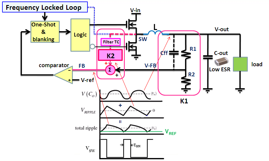
Figure 1. ACOT Buck converter control mechanism and operation
In an ACOT control system, the output feedback voltage
does not provide a linearly changing signal like it does in current mode converters,
but rather a dynamically changing modulation signal for the hysteretic control
mechanism. As a result, conventional open loop phase margin analysis (performed
by inserting a sweep signal between the output and the feedback network) interfere
with the hysteretic control loop and yield results quite different than a standard
current mode or voltage mode converter. Conclusions based on these conventional
measurements may be incorrect. See examples in figure 2 below: Open Loop gain/phase
of Current Mode system (left) vs. ACOT system (right).
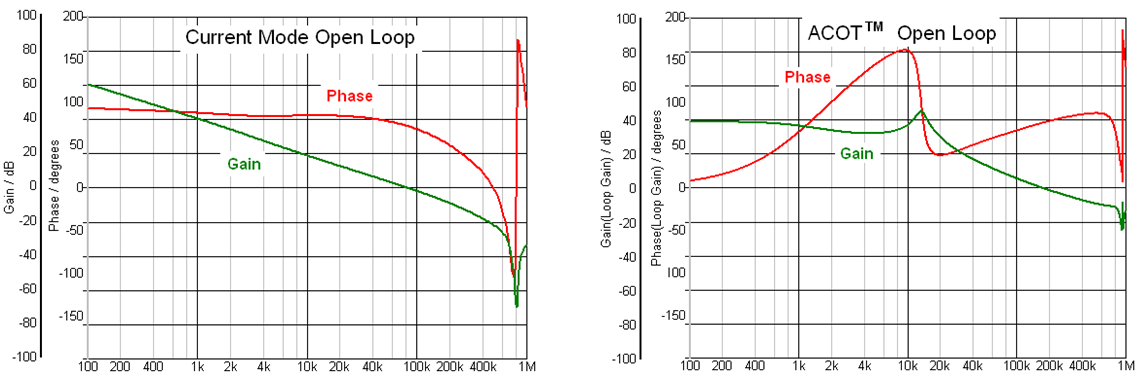
Figure 2. Open loop gain/phase simulation of current mode and ACOT converters
show very different results
However, ACOT converters may be mathematically analyzed
in frequency domain by calculating their closed loop response: This
is done by adding the sine-wave sweep signal to the control input (at
Vref) and viewing the Bode plot of the output voltage versus control input as
shown in figure 3.
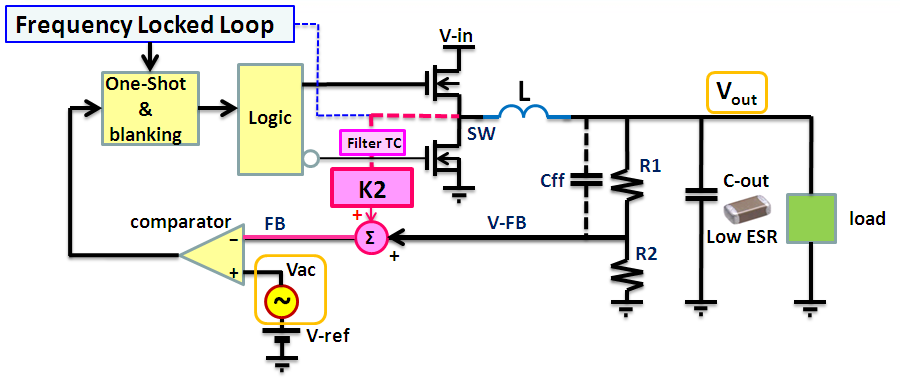
Figure 3. Closed loop measurement of ACOT Buck converter
This method of calculating the closed loop response of
ACOT provides accurate results, because the sweep insertion signal is added
to a stable DC control signal and therefore does not interfere with the dynamically
changing modulation signals. The results are very comparable to that of Current
Mode converters, as shown in examples in figure 4: Closed Loop Gain/Phase of
Current Mode (left) vs. ACOT (right).
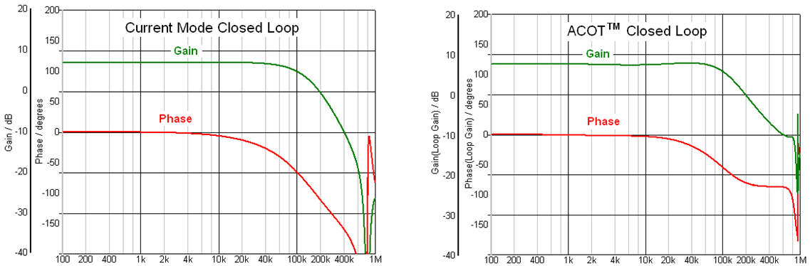
Figure 4. Closed loop gain/phase simulation of current mode and ACOT converters
show similar gain and phase curves
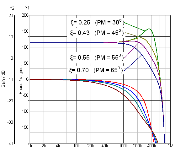
Figure 5. Closed loop gain-phase with various damping factors (based on 800kHz
current mode Buck converter)
In closed loop mathematical analysis, the system stability
can be found by observing the closed loop response.
Flat gain response is
considered stable (critically damped or over-damped response), while severe
peaking in the gain with abruptly decreasing phase around resonance frequency
(under-damped response) corresponds to low phase margin in the system open loop
gain. See figure 5: Examples of closed loop gain/phase with various damping
factors.
Very low damping factor ξ will correspond with low phase margin.
To secure an open loop phase margin above 45°, the closed loop damping factor
ξ should be > 0.43.
2. ACOT Buck Converter Stability Boundaries
Conventional Constant On Time (COT) Buck converters need
a feedback signal that is in phase with the inductor current for stability.
It is for this reason that conventional COT converters use output capacitors
with some minimum ESR, because this ESR output ripple is in phase with the inductor
current. When using very low ESR output capacitors, the ESR output ripple becomes
too small to be useful and the remaining feedback signal has too much phase
delay. The result is instability and oscillation.
ACOT converters overcome
this limitation because they utilize an internal ripple generator which is in
phase with inductor current and is added to the feedback signal. This permits
the use of very low ESR output capacitors, and means that ACOT converters will
be stable over a wide range of applications and operating conditions. However,
there are some conditions that could result in unstable switching:
a.When very small output capacitors (< 5μF) are used,
the larger (phase shifted) output ripple may cause sub harmonic instability
because the output ripple amplitude is much bigger than internally generated
ripple. In normal applications C-out ranges from 22μF ~ 66μF so this is usually
not a problem.
b.In higher duty-cycle applications (higher output voltages
or lower input voltage), the internal ripple signal will increase in amplitude.
Before the ACOT converter can react to an output voltage fluctuation, the voltage
change on the feedback signal must exceed the internal ripple amplitude. Because
of the large internal ripple in this condition, the response may become too
slow, and may show an under-damped response. This can cause some ringing in
the output, and is especially visible at higher output voltage applications
like 12V to 5V where duty-cycle is high and the feedback network attenuation
is large, adding to the delay.
External components that influence this behavior:
- Higher feedback network attenuation (higher output voltage applications)
will make it worse
- Larger output capacitance will make it worse because
output fluctuations are also smaller and delayed
- Larger inductor values
will make it worse because the energy the system can deliver in one Ton period
is lowered
For these applications, adding a feed-forward capacitor (Cff)
across the upper feedback resistor is recommended. This increases the damping
of the control system. See figure 6 below.
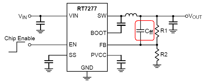
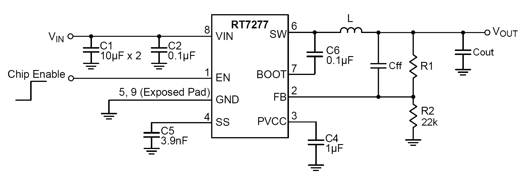
Figure 6. ACOT converter schematic. Feed-forward capacitor Cff
can be used to increase system damping
The Recommended Application Components table in the ACOT
device datasheet will show typical values for Cff that will result
in stable operation. For optimal stability and total application verification,
Richtek has developed a design tool that can help determining the optimal value for Cff.
3. ACOT Stability Design Tool
The ACOT stability design tool can be used to calculate
the optimal value of the feed-forward capacitor Cff for any ACOT
Buck converter application.
After entering
the application parameters, (ACOT device, input & output voltage, output
capacitance and ESR, inductor value), the tool will first calculate the feedback
resistors, and then the control system closed loop response without feed-forward
capacitor. It will then determine the optimal Cff value for best
system damping.
The user can select different feed-forward capacitor
values and see the impact on closed loop response. The damping factor ξ will
be calculated and can be used to judge the overall converter stability.
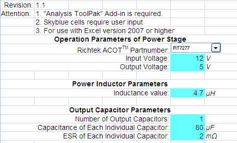
Figure 7. Circuit parameter fields. This example is a 5V application with
80μF of ceramic output capacitors.
For this application, the designer will need to add
some feed-forward capacitance.
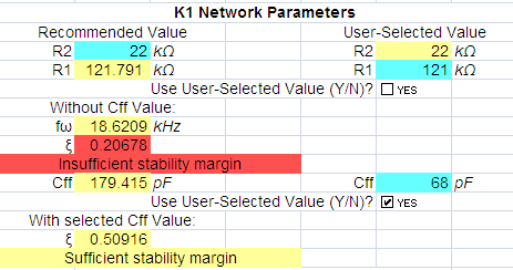
Figure 8. Calculation of the feedback network and damping
factor ξ without and with Cff. Optimal value for Cff is
180pF, which will result in a damping factor > 0.707. When using Cff
= 68pF, the damping factor will be 0.509, which is slightly under-damped condition,
but provides sufficient stability margin.
The tool will plot the gain &
phase for both conditions.
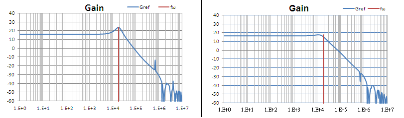
Figure 9. Closed loop gain without Cff (left) and with Cff
= 68pF (right)
4. ACOT Buck Converter Stability Testing
Although ACOT converters can be mathematically analyzed
by closed loop calculation, this method cannot be used for practical testing,
because the converter control input (Vref) is not accessible from
outside the IC. However because of the relation between frequency domain closed
loop damping factor and time domain load transient characteristics, ACOT converter
stability can be readily measured by applying fast load steps and observing
the resulting output voltage fluctuation.
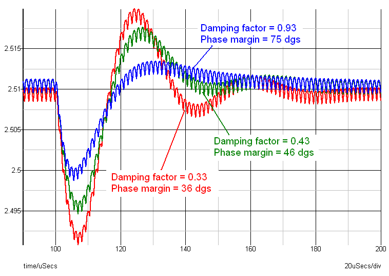
Figure 10. ACOT Buck converter output voltage during load step.
Figure 10 at the left shows a buck converter output voltage
fluctuation during a fast load step transient with differing damping factors
(ξ).
It is apparent that the transient output voltage during a step-load
will show different behavior based on the dampening factor used:
A system
with sufficient damping (blue waveform) will not show any ringing, and the output
voltage will smoothly move to its final value. This correlates with a very good
phase margin, in this case ~ 75 degrees.
When the damping factor is lowered,
ringing starts to appear in the transient response (green waveform) and the
correlated phase margin is low but acceptable for most applications at 46°.
As the dampening factor is reduced further, ringing increases and phase margin
erodes. (Red waveform)
For ACOT converters, damping factors of > 0.43
are acceptable, and a damping factor > 0.50 will guarantee stability including
device tolerances. This means that output voltage may show some slight ringing,
which quickly damps out in < 1.5 cycles.
5. Practical Measurement Setup
To check stability via a fast load transient, a load step
with a speed that exceeds the converter bandwidth must be applied. For ACOT,
loop bandwidth can be in the order of 100 ~ 200kHz, so a load step with 500nsec
maximum rise time (dI/dt ≈ 2A/μsec) ensures the excitation frequency is
sufficient. (> 300kHz). The actual amplitude of the load step is not critical,
generally a current step of 20 ~ 30% of max load is recommended. So for a 3A
converter, a 1A peak-peak current step with variable DC value is suitable. For
converters with enhanced light load efficiency mode, it is important that the
converter operates in PWM mode, outside the light load efficiency range, and
below any current limit threshold. For these reasons, a load transient from
1/3 to 2/3 of maximum load is reasonable.
Most electronic loads cannot
generate very fast load steps. For these cases a simple tool can be used to
generate fast load steps. Figure 11 below shows an example of a tool that can
be used to generate fast load steps: It consists of a MOSFET switch driven by
a pulse generator. The MOSFET switches a resistor to the converter output. Another
resistor is connected to the output directly to set the static load condition.
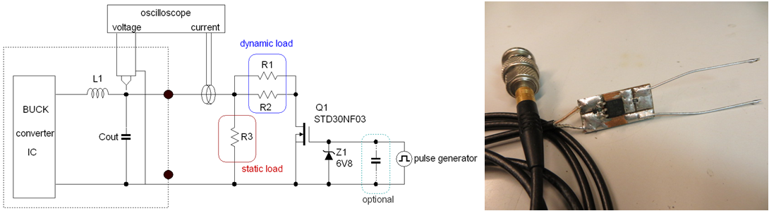
Figure 11.
This tool can create very fast dI/dt, (rise times of ~
50nsec) but these speeds can induce ringing which is not due to converter stability
but due to Buck converter input ringing. (supply lines and ceramic input cap,
PCB traces etc). Increasing the step-load rise times to ~ 500nsec will reduce
this effect. The driving speed of the pulse generator determines the switching
speed. To slow down speed, a capacitor can be added at the MOSFET gate to reduce
the driving speed. As an extra precaution, a 220μF electrolytic capacitor can
be added in parallel with the Buck input capacitor close to the IC, to damp
any ringing from input side. To avoid too high power dissipation in the dynamic
load resistors, keep the pulse load duty factor low, around 20% or less.
Figure 12 shows the typical measurement setup.
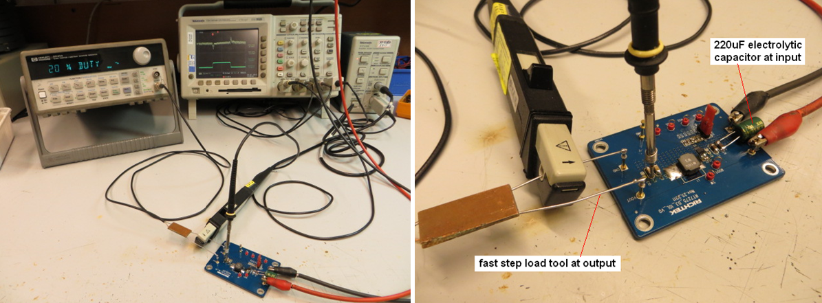
Figure 12.
Some examples of fast step response measurements are shown
below:
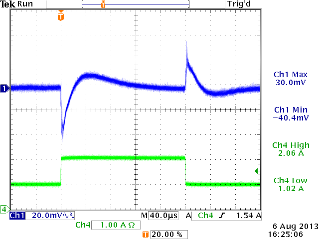
(Based on RT7277GSP in 5V and 1.8V application)
|
5V application:
|
|
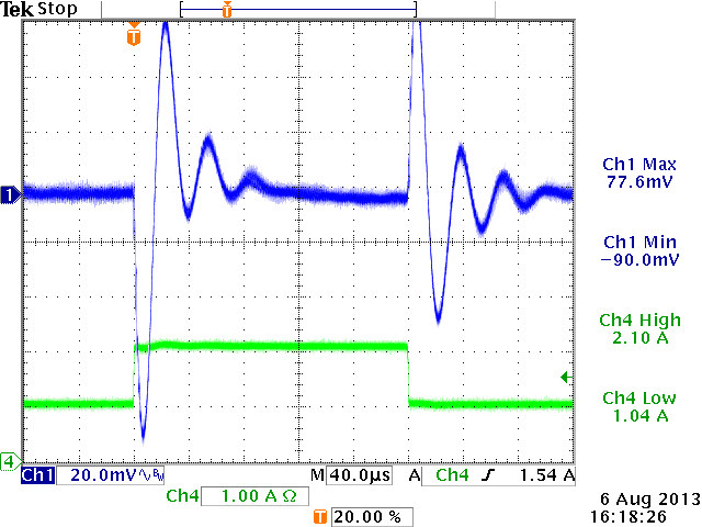
12V→5V,
Cout=60μF, L=4.7uH, Cff = 0pF
|
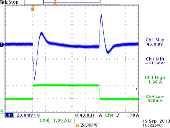
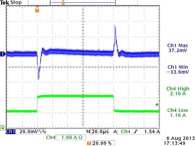
12V→5V,
Cout=60μF, L=4.7uH, Cff = 39pF
|
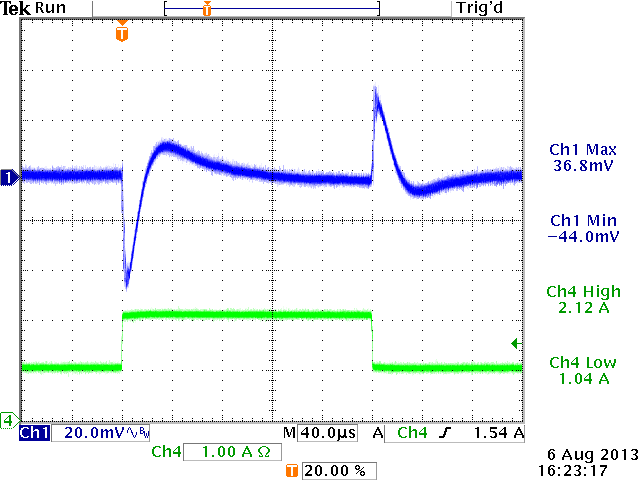
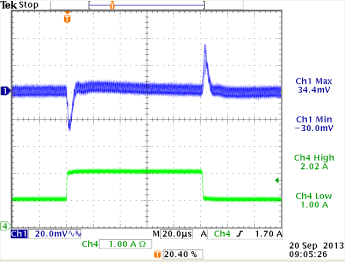
12V→5V,
Cout=60μF, L=4.7uH, Cff = 82pF
|
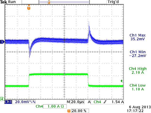
12V→5V,
Cout=60μF, L=4.7uH, Cff = 150pF
|
|
|
|
|
|
|
ξ = 0.24 (from design tool)
severe under-damped
|
ξ = 0.44 (from design tool)
under-damped but OK
|
ξ = 0.65 (from design tool)
sufficiently damped: OK
|
ξ > 0.707 (from design tool)
(actual ξ value ~ 1.1)
Over-damped :
Optimal stable
|
|
1.8V application:
|
|
12V→1.8V,
Cout=44μF, L=2.2uH, Cff = 0pF
|
12V→1.8V,
Cout=44μF, L=2.2uH, Cff = 15pF
|
12V→1.8V,
Cout=44μF, L=2.2uH, Cff = 100pF
|
12V→1.8V,
Cout=4.7μF, L=2.2uH, Cff = 0pF
|
|
|
|
|
|
|
ξ = 0.35 (from design tool)
under-damped
|
ξ = 0.43 (from design tool)
under-damped but OK
|
ξ = 0.64 (from design tool)
sufficiently damped: OK
|
ξ = 0.11 (from design tool)
Cout too small: sub-harmonic oscillation.
Increase Cout.
|
6. Precautions When Making Very Fast Load Step Measurements
|
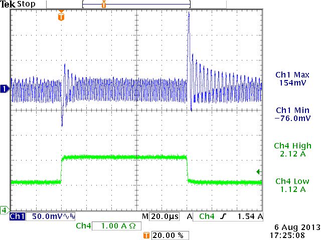
1.2V application with
large fast step:
Blue = Vout,
Green = load current
Cyan = SW signal
|
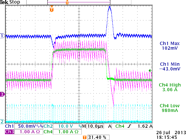
1.2V application large fast step
Purple = Inductor current,
Green = load current
Cyan = SW signal
|
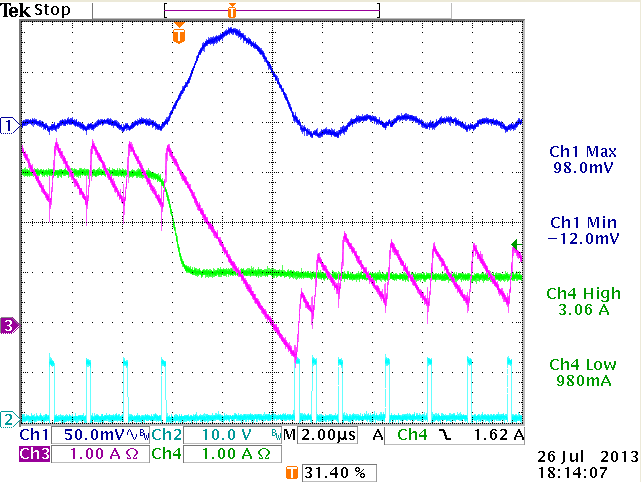
Zoom in to soar effect:
The inductor current drops slower than load
current, thereby charging the output capacitor
|
|
|
|
|
|
V-out shows overshoot at step-load falling
edge (the overshoot can vary, depending whether it happens during
Ton or Toff)
|
Capture of max soar with inductor current
added.
|
Soar on output happens due to slow discharge
of inductor current. Soar is not related to stability.
|
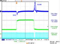
During step-load rising edge there will be an output voltage
sag effect, where undershoot is mainly determined by the reaction speed of the
converter and the max duty-cycle that the converter can achieve.
During
fast load step falling edge there will be an output soar effect, where the output
can show some overshoots because the inductor current cannot ramp down fast
enough and charges the output capacitor.
Output soar is mainly determined
by load step amplitude, inductor value and output capacitance, as the ACOT converter
will temporarily go into 0% duty cycle mode. Soar effects are especially visible
in low output voltage supplies, where inductor current dI/dt is low due to Vo/L
is low. These effects should not be mistaken for instability.
7. Summary
ACOT converters incorporate an internal ripple generator
which makes them suitable for use with very low ESR output capacitors. As result,
ACOT converters will be stable over a wide range of applications and operating
conditions. In some applications (especially higher output voltage applications),
ACOT converters may show under-damped response. By adding a feed-forward capacitor,
the system damping can be increased, to achieve a well damped response.
To determine the optimal value of the feed-forward capacitor, a design tool
is available which can calculate the required feed-forward capacitor for any
application. The design tool will also calculate the closed loop system damping
factor, which can be used to judge the system stability.
For practical
stability measurements, time domain measurements using fast load steps are recommended.
In these step-load measurements, stability can be judged by observing the output
voltage fluctuation during the load step. Well damped systems will show minimal
ringing in the output voltage during fast load steps.
Applying traditional
Open Loop phase margin measurements to ACOT Buck converters can show misleading
results, because ACOT converters are non-linear hysteretic topology control
systems, and the feedback signal from output is not a linearly changing signal
like in current mode converters, but rather a dynamically changing modulation
signal for the hysteretic control mechanism. For this reason, traditional Open
Loop phase margin measurements to analyze ACOT converter stability are not recommended,
as conclusions based on these measurements may not be accurate.