Power Management for Video Doorbell
Abstract
IoT has become more and more important in our life. The doorbell is one of the IoT equipment. Traditional doorbells are only available for communication or video display, but the modern doorbell can provide many functions including video recording, RF connection (WiFi, BT). These functions bring our life more convenience than before. This document introduces the system overview, different power source with pros and cons, and power management selections for video doorbells.
About the power management, this document introduces the power delivery of USB Type-C, battery charger, and gauge for battery management, and buck/boost DC-DC converters for increasing the system efficiency. These power management solutions can help increasing the reliability and lifetime of doorbells.
1.
Introduction of Video Doorbell
The traditional doorbell is only available for communication and video display when someone presses the doorbell. However, as an IoT equipment, the modern video doorbells have many features, such as video recording, monitoring the outdoor environment all day, and recording the video in memory cards or a cloud drive, as shown in Figure 1. Moreover, the doorbell can be remote controlled by mobile devices through RF circuits. When users are not at home, they can talk to visitors via mobile phone.
Generally, there are two considerations before installing a video doorbell. The first is the power source and the other is the internet. Due to the popularity of Wi-Fi and BT, the internet connection of a video doorbell is not a problem. As for the power source, if the power outlet is not designed in advance, the battery-powered solution is the most convenient way to install because no extra cable required.
At normal usage condition, the battery life of battery powered smart doorbell is about six months. How to extend the battery life becomes an important consideration.
With so many functions in the modern doorbell, the power consumption is more than traditional doorbell. Too much heat in the doorbell will cause the reliability reduction and shorter lifetime, so the power management is very essential.
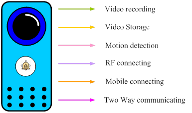
Figure 1. Function of Video Doorbell
Figure 2 is the function block of a video doorbell. The power source of doorbells can be an AC power source, battery only, or both. The camera sensor is for video recording. Video recording can be set recording all day or recording after this function enabled. The PIR sensor can detect the human motion. When a stranger stands in front of a doorbell, the PIR sensor detects the motion and then enable the system. This function can help decrease system power consumption. Flash memory is for the data storage. it can store the video recording data and overwrite the old data to continuously record the new video without interrupt. Video data can be uploaded to the cloud drive too. Speaker and microphone provide communication in the doorbell. WiFi is the key function of this product. WiFi helps users to connect to the video doorbell by mobile phone. Thus, we can know the outdoor situation, or communicate with visitors in front of the doorbell though mobile phones. Furthermore, it can notify us when something is abnormal or out of order. WiFi is the key function of IoT equipment.
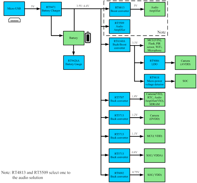
Figure 2. Power Tree of Battery Powered Video Doorbell
2.
The Power Source of Doorbell
There are three kinds of power sources for the video doorbell, one is 12VAC to 24VAC source, another is the battery, and the other is the combination of AC source and battery. 12VAC to 24VAC source is from the distribution board of houses and it is a permanent power source. The most important design consideration of AC source is the system efficiency. We can get the better thermal performance and save electricity by increasing system efficiency.
The other source is the battery. The main advantage of battery powered doorbells is easy install, no extra cables necessary to connect. However, the quiescent and shutdown current have to be very small to extend the usage time. Otherwise, the battery will run out quickly and users have to charge the battery frequently. Battery power only will also limit the function due to the need for low power design.
The last kind of power source is the combination of AC source and battery. During normal operation, the doorbell is supplied by AC source. The doorbell will change to battery supply mode in case the power outage happens. The back-up battery means a battery charger is necessary, which means more cost.
Table 1. Comparison between Three Kinds of Power Source
|
Power Type
|
Pros
|
Cons
|
|
AC
|
- Permanent power
- High system performance
|
- Need AC-DC adapter
- Install needs cable connection
|
|
Battery
|
- Free location
- Easy installment
|
- Need to change the battery
- Performance would be limited due to low power design
|
|
AC + Battery
|
- Battery can be backup during power outage
|
- Need AC-DC converter
- Install needs cable connection
- High cost
|
3. Power Management
3.1. Switching Charger
A switching charger is necessary for the doorbell with combined power source. When the AC source is present, the switching charger can charge the battery and provide power to system. If the battery fully charged, the power management feature can supply the system load from the AC source. The battery will not be charged or discharged frequently, which extend the battery life cycle. Once the power outage happens, the doorbell can be supplied by the battery. The doorbell can work normally all the time.
The switching charger, RT9471 can achieve the goals above. Moreover, the RT9471 can support 3.9V to 13.5V input voltage, maximum 3A fast-charge to reduce the charge time, minimum 50mA pre-charge current when the battery is deeply discharged.
The RT9471 Efficiency is up to 92% at 5V input to 4.2V battery with 2A charge current to prevent too much heat in the doorbell, as shown in Figure3 and Figure 4.
Figure 3. RT9471 Charger Efficiency
Figure 4. RT9471 Power Loss vs. Charging Current
RT9471 features battery charging with high regulation voltage accuracy, only ±0.5% tolerance. This improves the battery charging safety and the fully charged battery capacity (SOC) will be about 2% higher than that with charge voltage accuracy of ±1%, as shown in Figure 5.
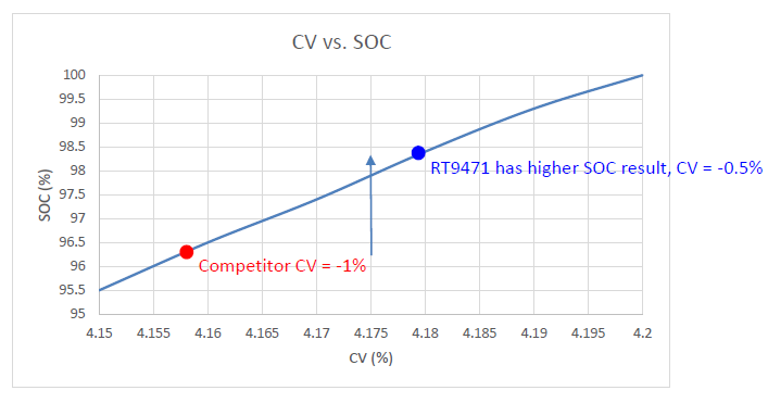
Figure 5. SOC Compared with Competitor
3.2. Battery Gauge
The smart doorbell is usually in standby mode and consumes low quiescent. Occasionally, when a guests visits and presses the doorbell, the smart doorbell switches to normal operation and suddenly consumes large current. Monitoring the battery status during light and heavy load and reporting battery capacity is very important.
The smart doorbell is an outdoor product. In tropical countries, the ambient temperature is always hot; in cold countries, ambient temperature can be quite low; and in countries with desert climate, the ambient temperature fluctuates considerably day and night. No matter which ambient condition, the battery status and capacity all have to be monitored accurately by the battery gauge IC.
Employing Fuel Gauge IC for Battery Management
In view of the above mentioned application challenges, Richtek’s fuel gauge RT9426A, is the solution. RT9426A is a Li-Ion and Li-Polymer battery fuel gauge IC for single-cell applications. It provides accurate voltage measurement with error within ±7.5mV and current measurement with error within ±1%. The best capacity estimation error is within 1%. The RT9426A power consumption is 14µA for normal mode and 5µA for sleep mode. Figure 6 is a simplified application circuit for RT9426A.
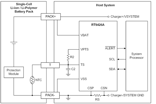
Figure 6. RT9426A Simplified Application Circuit
Figure 7 shows the performance of capacity estimation for a wearable device with 7-days usage situation. (4.4V/230mAh) Figure 8 shows the corresponding battery voltage & current profile of Figure 7. There is no accumulation error on SOC estimation during long system suspend and light load period.
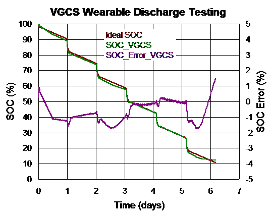
Figure 7. Performance of Capacity Estimation for Wearable Device with 7-Days Usage
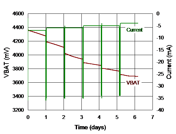
Figure 8. Battery Voltage & Current Profile of Wearable Device with 7-Days Usage
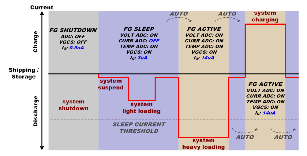
Figure 9. RT9426A Power Mode vs. System Loading
Monitoring Battery Status and Capacity with Ultra-Low Power
The common battery capacity for smart doorbell is around 5200mAh. Considering a battery life of 6 months, the RT9426A could save 3% system power consumption and extend about 139 hours compared with similar competitor solutions which have Iq in the range of 50uA. Figure 9 shows RT9426A will change its power mode according to system loading.
Accurate Capacity Estimation under Dynamic Load
As mentioned above, smart doorbells usually operate in standby mode with low quiescent. When the doorbell is activated, a large dynamic load will required by the system. The RT9426A is equipped with VGCS (VoltaicGaugeTM with Current Sensing) algorithm. It provides accurate battery capacity report by battery current sensing in short-term. While the smart doorbell is in standby mode, light load is required by the system, RT9426A estimates the battery capacity according to the difference and trend of battery voltage in long-term.
RT9426A enters sleep mode automatically while detecting the system is in standby mode. It helps extending the battery life. When the system switches to normal operation and the load increases, RT9426A switches to active mode automatically. This feature satisfies the system behavior of smart doorbell.
Compact and Min BOM
The RT9426A uses a tiny package of WL-CSP. Minimal BOM application includes only one sense resistor and one capacitor, so it’s easy to integrate to system main board.
Supporting Temperature Compensation and Battery Aging Correction
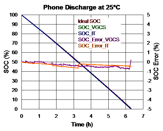
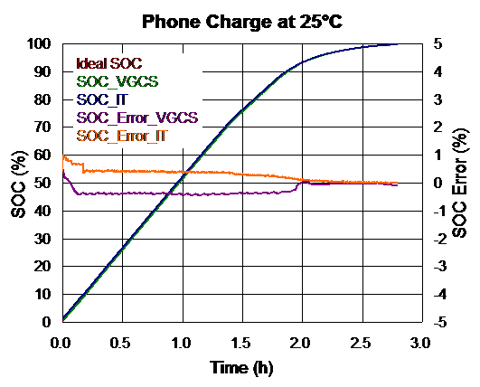
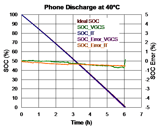
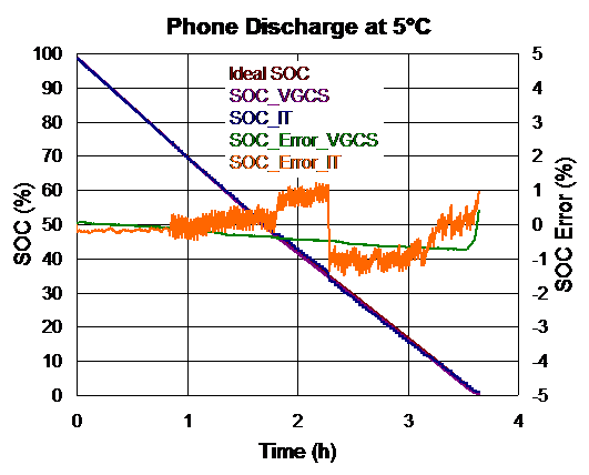
The RT9426A supports ambient temperature compensation when estimating battery capacity. By temperature compensation, battery capacity under different ambient temperature will be smoothly and continuously reported. Figure 10~13 show the SOC performance at 25°C/40°C/5°C. Moreover, the RT9426A monitors battery health and corrects battery capacity when battery aged. As a result, the RT9426A always keeps high accuracy of battery capacity report.
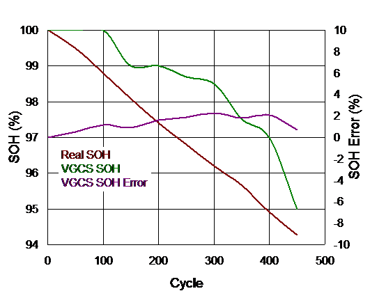
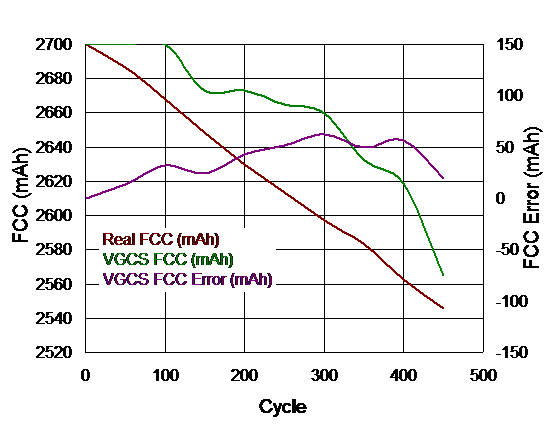
RT9426A compensates battery capacity estimation for the degradation of battery. It controls the capacity error within 2%. Figure 14 to 15 show FCC & SOH performance of 450 cycles usage. Referring to the Figure 16 below shows an example of 4.4V/2700mAh battery. The SOC error stays within 2% after 450 cycles of usage.
|
|
|
|
Figure 10. SOC performance comparison of discharging at 25°C
|
Figure 11. SOC performance comparison of charging at 25°C
|
|
|
|
|
Figure 12. SOC Performance Comparison of Discharging at 40°C
|
Figure 13. SOC Performance Comparison of Discharging at 5°C
|
|
|
|
|
Figure 14. FCC Performance of 450 Cycles Usage
|
Figure 15. SOH Performance of 450 Cycles Usage
|
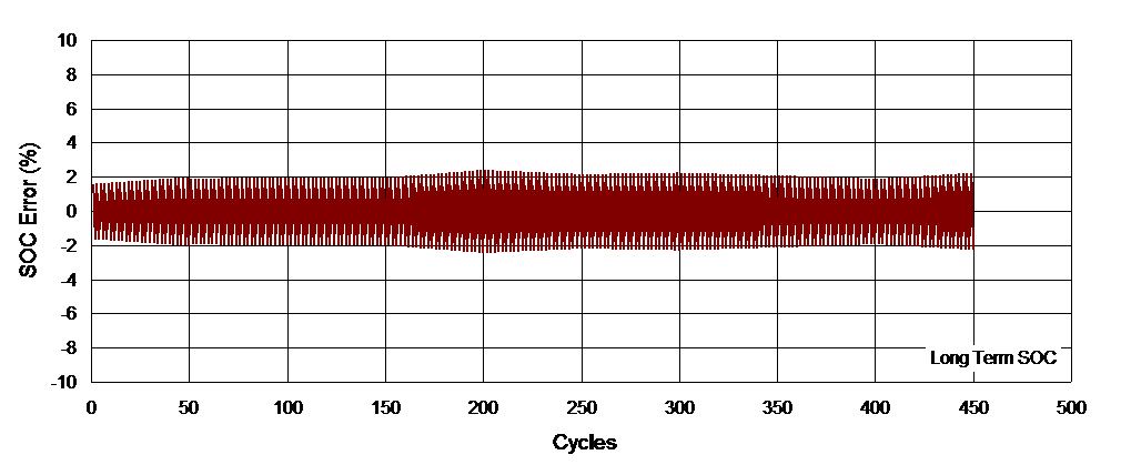
Figure 16. SOC Performance of 450 cycles usage
3.3. DC-DC Converter
In this chapter, the DC-DC solutions for the video doorbell application are proposed, and different cases of power solution are discussed. It shows an overview of recommended power solutions and their key features for the video doorbell application.
- RT4813 : High Efficiency Boost Converter
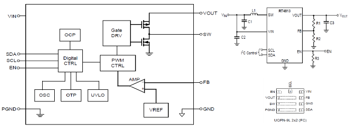
Figure 17. RT4813 Block Diagram, Simplified Circuit and Package
♦Feature
- Low Quiescent :120µA
- Small Size : UQFN-9L 2x2mm2
- High Efficeincy : 93.9%@5V/6mA
- Wide VIN Range from 1.8V to 5.5V
- RT5707 : Ultra-Low Quiescent Current HCOT Buck Converter
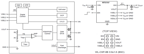
Figure 18. RT5707 Block Diagram, Simplified Circuit and Package
♦Feature
- Low Quiescent : 0.46µA
- Small Size : WL-CSP-8B 0.9x1.6mm2
- High Efficeincy : 94.6%@1.8V/180mA
- High Efficeincy : 87.8%@1.2V/120mA
- Internal Compensation for Optimized Transient Response
- RT5713 : Tiny, Ultra-Low Quiescent Current HCOT Buck Converter
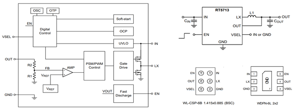
Figure 19. RT5713 Block Diagram, Simplified Circuit and Package
♦Feature
- Low Quiescent : 0.46µA
- Small Size : WL-CSP-6B 1.415x0.885mm2, WDFN-6L 2x2mm2
- High Efficeincy : 85.4%@1.1V/280mA
- High Efficeincy : 82.4%@0.8V/40mA
- Internal Compensation for Optimized Transient Response
- RT6160A : Low Quiescent, High Efficiency 3A Buck-Boost Converter with I2C Interface

Figure 20. RT6160A Block Diagram, Simplified Circuit and Package
♦Feature
- Low Quiescent : 2μA
- Small Size : WL-CSP-15B 1.4x2.3mm2
- High Efficeincy : 95.2%@3.3V/1.3A
- 1μA Non-Switching Low Quiescent Current
- Ultra-Sonic Mode Operation to Avoid Acoustic Noise
- Automatic PFM Mode and Forced PWM Mode Selection
- RT9086 : 250mA, Ultra-Low Noise, Low Quiescent Current, LDO Regulator
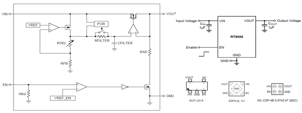
Figure 21. RT9086 Block Diagram, Simplified Circuit and Package
♦Feature
- Low Quiescent : 16μA
- Small Size : WL-CSP-4B 0.67x0.67mm2, ZQFN-4L 1x1mm2, SOT-23-5
- High PSRR : 85dB@1kHz
- Very Low Dropout : 120mV
- Excellent Noise Immunity
- Stable with a 1μF Input and Output Ceramic Capacitors
- RT8092 : 3MHz 4A High Efficiency Step-Down Converter with I2C Interface
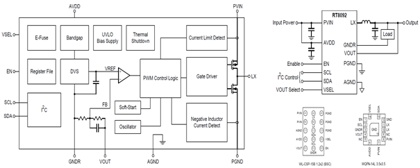
Figure 22. RT8092 Block Diagram, Simplified Circuit and Package
♦Feature
- Low Quiescent : 15μA (Low Power Mode)
- Small Size : WL-CSP-15B 1.2x2mm2, WQFN-14L 3.5x3.5mm2
- High Efficeincy : 82.28%@0.75V/1A
- Auto-PSM/PWM or Force-PWM Selectable
- Support Remote Ground Sensing for Accurate Output Voltage
Section 1 : How to Improve System Efficiency by Choosing Proper Converter
In this section, we introduce the system power design to increase more efficiency. The power source is the battery with typical voltage 3.8V, and the capacity is about 5200mAh. The power tree is as shown in Figure 23. Due to the use of some LDO’s, this topology is not the best structure to get high system efficiency. RT4813, RT6160A, RT9086, RT5707, RT5713 and RT8092 are proposed in this power solution.
Topology 1 is the power tree and the system efficiency is 86.8%.
Power converter : 1Boost + 1Buck-Boost + 4Buck + 3LDO
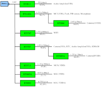
Figure 23. Power Tree of Topology1
Table 2. Efficiency of Topology 1
|
Channel
|
Efficiency (%)
|
|
RT4813 Boost_5V
|
93.9
|
|
RT6160A Buck-Boost_3.3V
|
96.1
|
|
RT5707 Buck_3.3V
|
89.6
|
|
RT9086 LDO_2.8V
|
84.8
|
|
RT5707 Buck_1.8V
|
90.8
|
|
RT9085A LDO_1.2V
|
66.6
|
|
RT5713 Buck_1.1V
|
85.4
|
|
RT9085A LDO_0.8V
|
21.1
|
|
RT8092 Buck_0.75V
|
82.28
|
|
System Efficiency (active mode)
|
86.8
|
In Topology 2, we replace RT9086 with RT5707 to improve the efficiency. This power rail’s efficiency increases from 66.6% to 87.8%. Furthermore, the WiFi power is supplied by RT6160A, which is introduced in section 2. By adjusting the power converter, the system efficiency is about 90.8%, which improves 4% of the system efficiency.
Power converter : 1Boost + 1Buck-Boost + 4Buck + 2LDO
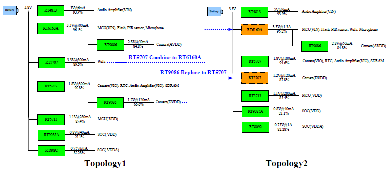
Figure 24. Power Tree for Topology 1 Changing to Topology 2
Table 3. Efficiency of Topology 2
|
Channel
|
Efficiency (%)
|
|
RT4813 Boost_5V
|
93.9
|
|
RT6160A Buck-Boost_3.3V
|
95.2
|
|
RT9086 LDO_2.8V
|
84.8
|
|
RT5707 Buck_1.8V
|
94.6
|
|
RT5707 Buck _1.2V
|
87.8
|
|
RT5713 Buck_1.1V
|
85.4
|
|
RT9085A LDO_0.8V
|
21.1
|
|
RT8092 Buck_0.75V
|
82.28
|
|
System Efficiency (active mode)
|
90.8
|
In topology 2, the efficiency of power rail for 0.8V is only 21.1%. To improve the efficiency, we replace RT9085A with RT5713 in topology 3, and the efficiency increases to 82.4%. As a result, the system efficiency increases to 92.5%.
Power converter : 1Boost + 1Buck-Boost + 5Buck + 1LDO
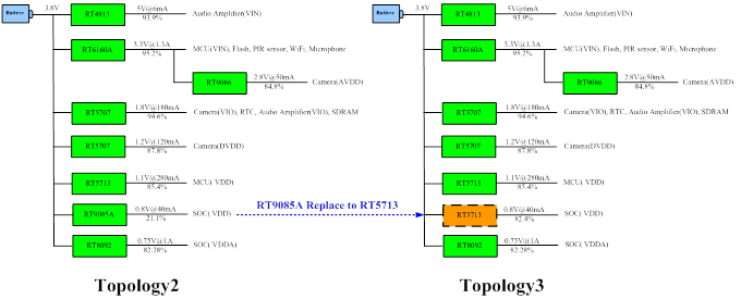
Figure 25. Power Tree for Topology 2 Changing to Topology 3
Table 4. Efficiency of topology 3
|
Channel
|
Efficiency (%)
|
|
RT4813 Boost_5V
|
93.9
|
|
RT6160A Buck-Boost_3.3V
|
95.2
|
|
RT9086 LDO_2.8V
|
84.8
|
|
RT5707 Buck_1.8V
|
94.6
|
|
RT5707 Buck _1.2V
|
87.8
|
|
RT5713 Buck_1.1V
|
85.4
|
|
RT5713 Buck _0.8V
|
82.4
|
|
RT8092 Buck_0.75V
|
82.28
|
|
System Efficiency (active mode)
|
92.5
|
We can estimate that how much the battery lifetime can be extended after the efficiency increases. With the battery with 5200mAh capacity as power source, the watt hour is 19.8Wh. The result is shown in Figure 26. The topology 3 has the longest battery life. Assuming that the doorbell is activated for 10s each time and 5 times a day, the battery life with topology 1 is about 180 days. With topology 3, the battery life can be extended with more than 10 more days.
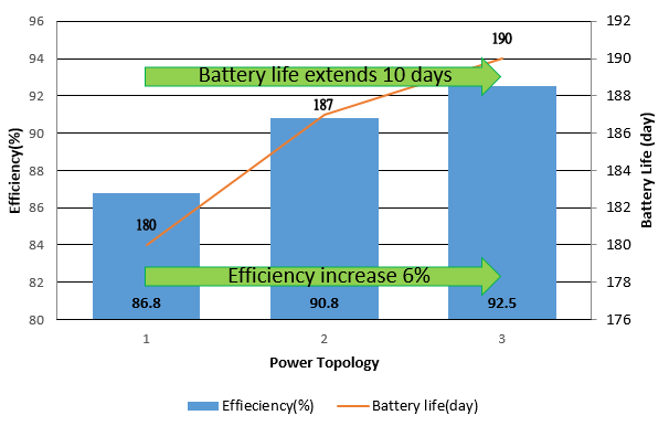
Figure 26. Battery Run Time Comparison between Different Power Topologies
Table 5. System Comparison
|
Parameter
|
Topology 1
|
Topology 2
|
Topology 3
|
|
System efficiency (%)
|
86.8
|
90.8
|
92.5
|
|
Battery run time (Day)
|
180
|
187
|
190
|
Section 2 : How to Select a Suitable Converter for 3.3V WiFi Application
In this section, the power converter selection for the 3.3V battery-powered WiFi application is introduced. Choosing a converter that is able to support wider battery voltage range is very important to extend the battery lifetime. Here are three types of converters for regulating 3.3V. One is a buck converter, another is a boost converter series with a LDO, and the last is a buck-boost converter.
Generally, the Li-Ion battery's useful voltage range is from 3V to 4.35V, which depends on the battery type. Selecting a buck converter to regulate 3.3V for WiFi application, if the battery voltage is lower than 3.3V, the stable WiFi function cannot be maintained.
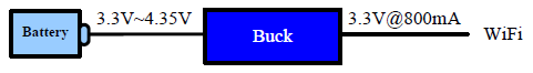
Figure 27. Buck Converter for WiFi
If a boost + LDO is chosen to regulate 3.3V, full range of battery voltage can be utilized. This structure can help extending the battery lifetime because it supports a wide battery range. However, this topology would suffer from low efficiency at Vin higher than 3.6V. When Vin is higher than 3.3V, the boost is operated in bypass mode, and the LDO regulates 3.3V. However, the higher voltage drop on LDO will cause lower efficiency. Therefore, this structure is less preferred.
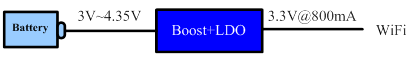
Figure 28. Boost Converter + LDO for WiFi
If a buck-boost converter is chosen to regulate 3.3V, it has the advantage of wide input range and high efficiency at high Vin. Thus, the buck-boost converter is the most optimal solution for 3.3V application.
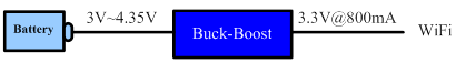
Figure 29. Buck-Boost Converter for WiFi
The Curves in Figure 30 are the battery run time estimation versus Vin. Buck converter has good battery run time at high Vin, but it can not work when Vin is lower than 3.3V. Boost + LDO can support whole Vin range, but its battery run time is shorter because of low efficiency at high voltage drop on LDO. Buck-boost converter has the longest battery run time and supports the whole Vin range. So this is the best topology for WiFi application.
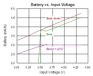
Figure 30. Battery Run Time vs. Input Voltage
Section 3 : Why We Need High PSRR LDO for Camera System
Figure 31 shows the power rail of ISP (Image sensor processor) for camera system. There are three rails, one is AVDD, another is DVDD and the other is VIO. Among them, AVDD is related to the image quality. The lower ripple on AVDD, the better image quality.
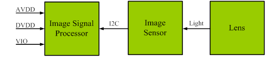
Figure 31. Block Diagram of Camera System
The following Diagram is the detailed analysis for the AVDD power rail. The image sensor gets the signal and then sends the signal to the ADC through the CDS and the Amplifier. The key factor of image quality is ADC, so the input ripple of ADC has to be as small as possible. Assuming that LDO input ripple is 5mV, and the LDO’s PSRR is 40dB, the LDO output ripple is 50µV. The PSRR of ISP is around 18dB, (a value which is based on different ISP vendors). Through the CDS, the output ripple decreases to 6.3µV. This ripple would be amplifed 30dB to the ADC by the internal amplifier of the ISP. Finally, the ADC’s input ripple will be 200µV, which just meets the ADC’s LSB resolution. Assuming that ADC’s reference voltage is 0.8V and the resolution is 12bit, if the voltage ripple for the ADC is larger than 200µV, it would result in increased ADC error.
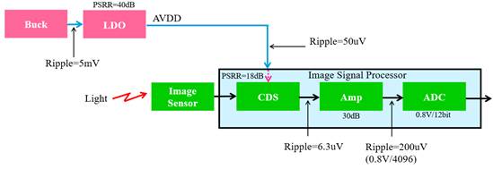
Figure 32. Power Requirement Deduction for AVDD
To achieve low noise, RT9086 with high PSRR and low noise is proposed for the AVDD power rail. RT9086 PSRR is 80dB@10kHz. According to the previous deduction of camera system, RT9086 can meet the ADC’s LSB voltage requirement with 500mV input ripple.
In other words, if buck converter output ripple becomes larger because of the component aging, temperature variation or load transient on this rail, the image quality would not be affected due to high PSRR of RT9086. In addition, RT9086 also has low quiescent design, which is suitable for battery application.
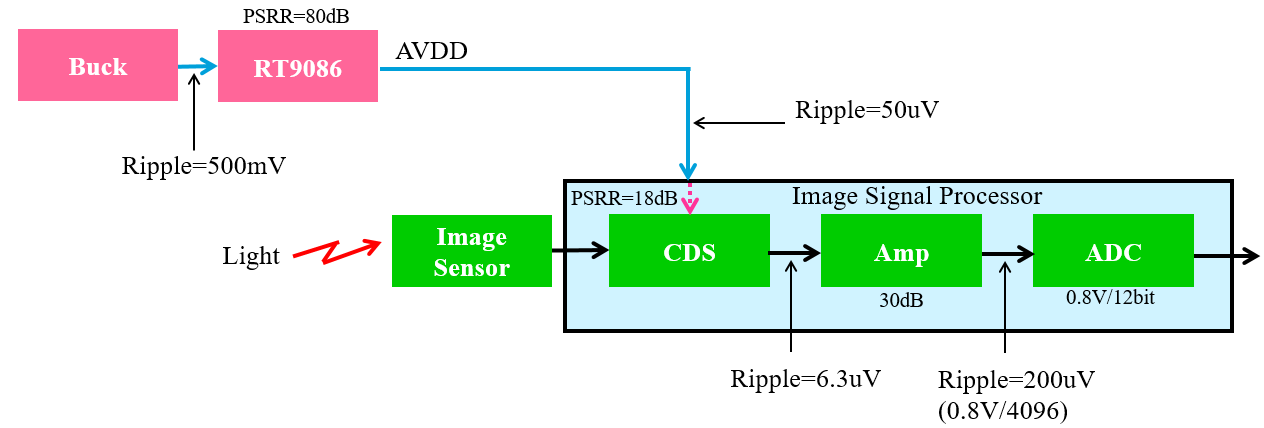
Figure 33. Power Requirement Deduction with RT9086 for AVDD
Figure 34. PSRR and Noise Density of RT9086
However, PSRR becomes worse at frequencies higher than 1MHz. If the LDO input ripple is coming from a buck converter with switching frequency 1.5MHz the ripple of buck converter will affect LDO output noise due to insufficienct PSRR at high frequency. In this case, it is recommended to add a small HF bead between the buck and the LDO. The bead + LDO input capacitor will act as a low pass filter to reduce HF ripple. Figure 35 is test result of adding HF bead to filiter out noise, after adding HF bead, LDO input ripple can reduce to 30mV, which is helpful for LDO output noise result when frequency exceeds 1MHz.
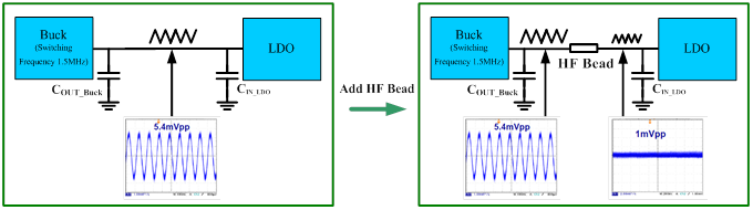
Figure 35. HF Bead Filter out HF Ripple
3.4. Audio Solution
Boost Converter with Low Battery Voltage
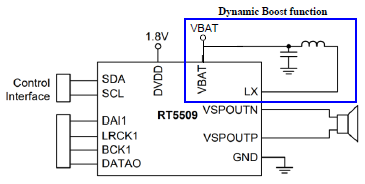
A smart amplifier is recommended for the doorbell product because this kind of product uses 1-cell battery, which limits the audio output power level with normal Audio amplifiers. Richtek recommends using RT5509 smart amplifier, which includes a Class-G boost converter as shown in Figure 36. It can supply 4.3W output power @ boosted 9.5V supply, in 8Ω Load, THD < 1% and it can provide several boost voltage levels based on the input signal level to increase the efficiency.
|
|
|
|
(a)
|
(b)
|
Figure 36. (a) Simplified Circuit of RT5509 (b) Class-G Boost Converter Behavior of RT5509
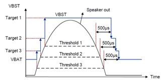
Speaker Protection
How can we achieve the highest sound pressure level (SPL)? Traditional amplifiers will limit the maximum power of speaker to ensure not to burn out the voice coil. Actually, we need to prevent speaker’s voice coil temperature becoming too hot and suspension structure damaged. The RT5509 smart amplifier integrates the current and voltage (I/V) sense. The I/V sense data allows IC to directly measure the speaker’s coil temperature and surround excursion for protection with the RT5509 internal control algorithm (see Figure 37).
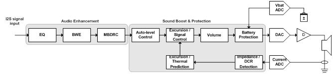
Figure 37. Speaker Protection Path of RT5509
Audio Effect DSP Functions
The RT5509 smart amplifier also supports audio effect functions, as shown in Figure 38, which can improve the sound quality and enhance sound pressure level (SPL).
Modifies frequency performance to achieve a flat response or match a target curve.
- 3-Band Dynamic Range Compression (DRC) :
Dynamic range compression (DRC) is an audio signal processing operation that can enhance quiet sounds or reduce the output level of loud sounds, thus reducing or compressing an audio signal's dynamic range.
- Band width Extension (BWE) :
Improve the bass sound effect on the thin-loudspeaker
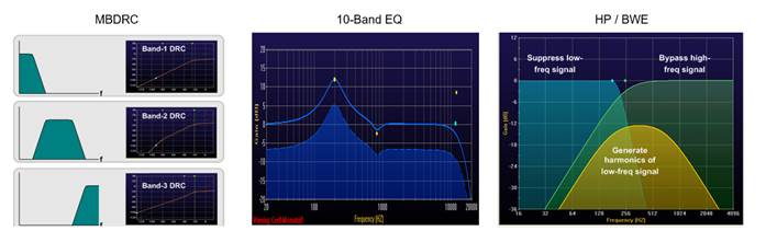
Figure 38. Audio Effect DSP Function of RT5509
3.5. How to Reduce Battery Charging
Time for Doorbell
Most video doorbells need 6~10 hours to charge the battery pack. They often make use of a micro USB-B connection. To reduce charging time, the higher power PD controller + cap divider + switching charger solution is proposed. In the next section the PD controller and cap divider are introduced.
PD Controller for Battery Charge
With USB-B interface, the adapter can only provide maximum power 7.5W (5V/1.5A), but via the new USB Type-C with Power Delivery (PD), many PD adapters can provide powers around 18~27W (9V/2A~3A), which means the battery can be fully charged in a shorter time.
Figure 39 shows an example of a high power charging system which makes use of the USB PD 3.0 Programmable Power Supply (PPS) feature. The switching charger will operate during the pre-charge and constant voltage mode of the charge cycle, but during the high power constant current cycle, the Capacitive Divider bypasses the switching charger. Charge current and voltage is now controlled by the USB PD adapter operating in PPS mode. All PD communication is handled by the RT1715 TCPC PD controller.
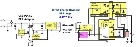
Figure 39. Structure of High Power Charging System
RT1715 is a TCPC PD controller, it can be applied to the doorbell for fast charge solution. The RT1715 is controlled by MCU and commands the PD adapter to provide 18~27W power. The TCPC series are compliant with ARM or 8051 platforms. MCU code size are shown in table 6.
Table 6. RT1715 PD Function MCU Code Size Table
|
ARM M0 Platform
|
8051 Platform
|
|
Code Size
|
Ram Size
|
Code Size
|
Ram Size
|
|
(byte)
|
(byte)
|
(byte)
|
(byte)
|
|
14.16k
|
369
|
15.57k
|
612
|
RT1715 also supports the programmable power supply (PPS) protocol, which can command the adapter to adjust the bus voltage and current accurately. With this protocol, a high-efficiency direct charging system can directly charge the battery using an adjustable bus voltage. The minimum bus voltage is 3.3V and the minimum bus input current is 1A.
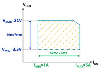
Figure 40. Programmable Power Supply (PPS) V/I Range
Table 7. Fixed Sources & Programmable Power Sources
|
Aspect
|
Fixed Source
|
Programmable Power Source
|
|
Constant Voltage mode
|
5V
9V
15V
20V
|
5V Prog (3.3V to 5.9V)
9V Prog (3.3V to 11.0V)
15V Prog (3.3V to 16.0V)
20V Prog (3.3V to 21.0V)
|
|
Current Step Size
|
Nominal 10mA
|
Nominal 50mA
|
|
Voltage Step Size
|
None
|
Nominal 20mV
|
|
Current Limit mode
|
None
|
Yes, nominal 50mA steps
|
|
Periodic RDO
(Request data object) during operation
|
No – does not apply
|
Yes, needed for PPS operation
|
Cap Divider Charger for Battery Charging
The cap divider charger is a high efficiency and high charge current charger. If the battery pack inside the doorbell is almost empty, the cap divider charger can charge the battery in a very short time, so that the doorbell can quickly be used again. Because the battery run time is very important in doorbell product, the cap divider charger must have low battery quiescent current feature.
The cap divider charger, RT9759 can achieve the goals above. The RT9759 supports maximum 8A charge current. The peak efficiency is up to 97.8%. At 5A charge current, the power loss is only 0.64W, so high current charging is possible without risk of too much heat in the doorbell. Moreover, the VOUT quiescent current is lower than 16µA.
Figure 41. RT9759 Charge Efficeincy
Figure 42. RT9759 Power Loss vs. Charge Current
Figure 43 is a fast charge system. Since RT9759 can only work in constant current mode, RT9759 has to be in parallel with switching charger RT9471 to execute the pre-charge mode and constant voltage mode. Detailed charge flow can refer to Figure 44.
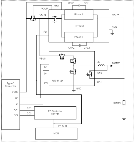
Figure 43. Simplified Charge System for Doorbell Power System
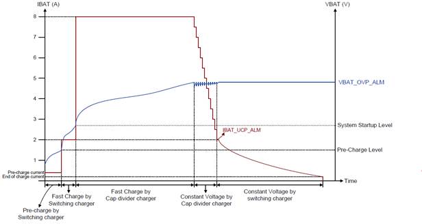
Figure 44. Charge Flow with Cap Divider Charger and Switching Charger
4. Conclusions
This document introduces the video doorbell application and power selection. For battery charger RT9471 is proposed, which can be operated in wide input range and owns high charge voltage accuracy. With high CV accuracy, it can improve state of charging to 98%, which represents more battery capacity.
To reduce the charging time of battery pack, we propose a fast charging solution with Power Delivery IC and a cap divider charger. Regarding the PD controller, we proposed RT1715 for USB-C solution. RT1715 can send command to the adapter for providing higher power than USB-B ports to reduce the battery charging time.
For the cap divider, we proposes RT9759. It supports up to 8A charging current at high efficiency and helps reducing the charging time. In combination with the switching charger RT9471, this charge solution can provide a fast and safe charge performance.
As battery gauge for battery-powered doorbell RT9426A solution is proposed. RT9426A not only helps extending the battery run life, but also provides reporting accurate battery capacity and status at any load conditions, ambient temperature and battery aging. For the DC-DC converter selection we discussed 3 sections, for improve the system efficiency and extend battery run time for 10 days, which helps enhancing users experience. In section 2, for doorbells with battery-powered only, a buck-boost converter is proposed to extend the battery lifetime for WiFi applications. In section 3, RT9086 is proposed due to its high PSRR and low noise capability for camera system. Furthermore, a power monitor for the SOC core voltage is necessary, so RT9818 is proposed because RT9818 has low quiescent current feature, and is suitable for the battery power system.
For the audio solution, we recommend RT5509 smart amplifier which has not only boost function, but also smart speaker protection. RT5509 can also enhance sound quality by audio effect DSP function too.
Table 8 shows the features and benefits of the proposed solutions.
Table 8. Summary of all Richtek Solution
|
Richtek Solutions
|
Features
|
Benefits
|
|
RT1715
|
Low Quiescent : 25µA
Small Size : WL-CSP-9B 1.38x1.34mm2
|
Reduce charging time by commending adapter to provide 27W (9V/3A)
|
|
RT9471
|
CV Accuracy : 0.5%
High Charge Efficiency : 92%@3.8V/2A
|
CV accuracy up to 0.5% improving SOC from 96% to 98%. 100mAh capacity obtained.
|
|
RT9759
|
Low Quiescent : 54µA
Small Size : WL-CSP-56B 3.35x3.35mm2
High Efficeincy : 97%@4.2V/2.5A
|
Support 8A charging current, reduce charging time about 25% compared with 2A charging current.
|
|
RT9426A
|
Low Quiescent : 14µA
Small Size : WL-CSP-9B 2.29x1.74mm2
|
Reduce 3% system power consumption, extend about 139 hours battery run time compared with competitor.
|
|
RT4813
|
Low Quiescent : 120µA
Small Size : UQFN-9L 2x2mm2
High Efficeincy : 93.9%@5V/6mA
|
Save 4mW, which enhances 13.9% efficiency than competitor with 80% efficiency in this rail.
|
|
RT6160A
|
Low Quiescent : 2µA
Small Size : WL-CSP-15B 1.4x2.3mm2
High Efficeincy : 95.2%@3.3V/1.3A
|
Buck-Boost for 3.3V power rail can extend battery run time for 0.5 hours compared with the buck converter.
|
|
RT9086
|
Low Quiescent : 16µA
Small Size : WL-CSP-4B 0.67x0.67mm2
High PSRR : 85dB@1kHz
|
High PSRR can help to reduce noise for camera system.
|
|
RT5707
|
Low Quiescent : 0.46µA
Small Size : WL-CSP-8B 0.9x1.6mm2
High Efficeincy : 94.6%@1.8V/180mA
High Efficeincy : 87.8%@1.2V/120mA
|
For 1.2V power rail, replacing RT9085A with RT5707 can improve efficiency from 66.6% to 87.8%, which saved 52.2mW in this rail.
|
|
RT5713
|
Low Quiescent : 0.46µA
Small Size : WL-CSP-6B 1.415x0.885mm2
High Efficeincy : 85.4%@1.1V/280mA
High Efficeincy : 82.4%@0.8V/40mA
|
For 0.8V power rail, replacing RT9085A with RT5713 can improve efficiency from 21% to 82.4%, which saved 113mW in this rail.
|
|
RT8092
|
Low Quiescent : 15µA (Low power mode)
Small Size : WL-CSP-15B 1.2x2mm2
High Efficeincy : 82.28%@0.75V/1A
|
Low power mode can save 171uW compared with the normal mode for this power rail.
|
|
RT5509
|
Boost Converter : 9.5V @ 4.3W/8Ω
Speaker Protection
Small Size : WL-CSP-48B 3.04x2.99mm2
|
Save cost of boost circuit for audio amplifier and provide powerful sound pressure level
|
|
RT9818
|
Low Quiescent : 3µA
High Accuracy : ±1.5%
|
Low quiescent current for extending battery run time.
|
5. Reference
[1]. RT4813 Datasheet
[2]. RT5707 Datasheet
[3]. RT9085A Datasheet
[4]. RT6160A Datasheet
[5]. RT9086 Datasheet
[6]. RT8092 Datasheet
[7]. RT9471 Datasheet
[8]. RT9759 Datasheet
[9]. RT1715 Datasheet
[10]. RT9426A Datasheet
[11]. RT5509 Datasheet
[12]. RT9818 Datasheet