Multi-Source Power Management Design
Abstract
Being able to use multiple component sources in one electronic power design can be a great benefit. Especially in times of semiconductor shortages, having multiple sources for a component can be a lifesaver that keeps production lines running. This application note will give some guidance and advice when selecting Richtek power management components and allow multiple sources to be used in one design.
1.
Introduction
The COVID pandemic has made it clear that the semiconductor supply chain is very sensitive to sudden changes in supply and demand, resulting in worldwide shortage of semiconductors in all fields, from consumer to automotive applications. Many company production lines had to reduce or even completely suspend their production due to lack of semiconductor components. As a result, these companies have been urgently trying to find alternatives for components in their designs. However, it is not always that simple to find alternatives for power management components: PCB layout may need to be changed, and several tests may have to be done before a new component can be introduced, while time pressure is huge due to possible production line stop. It can be a great benefit if multiple component sources are considered during the start of the design: at that time, pin compatible (P2P) parts can be selected, common component PCB footprints can be considered, and validation tests can be executed with multiple sources instead of a single source.
In this application note, some hints and guidelines are given when designing power management applications with multiple IC vendor sources.
2.
Low Voltage Buck converters multi source design
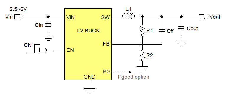
Small low voltage buck converters are often used to step down from a 5V or 3.3V rail to lower voltages like 1.2V or 1.0V at low current levels. They generally run at higher frequencies like 1.5 or 2.2MHz and use small size external components.
For these parts, (T)SOT23, DFN2x2-6L or SOT563 package are popular, and several supplier parts have the same pinout and can use the same PCB layout footprint. (T)SOT23 is most common, the DFN package has slightly better thermal properties, and the SOT563 has the smallest footprint. Richtek has many parts for this segment, but for multi-source design, the new generation ACOT® LV Buck is very suitable because this family is quite flexible regarding the external component choices and the package pinout is quite common.
2.1. External Component
considerations for ACOT® LV Buck
Feedback network
The feedback network impedance does not play a role in Richtek ACOT® converter stability; it works well at both low and high feedback network impedance. The feed-forward capacitor Cff should be reserved, as it will be needed in some cases, see below. If the other vendor part control topology and FB reference voltage is the same, it is quite possible that the feedback resistors can be the same for both parts.
Inductor value
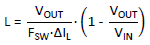
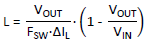
Generally, the inductor value is chosen based on a current ripple around 20 ~ 40% of the IC rated current according the formula:
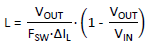
Richtek ACOT® topology can accept a wide range inductor values. Smaller inductor values will improve the load transient performance. Larger inductor values reduce the output ripple, but worsen the transient response.
Output capacitance
The recommended output capacitance value in the datasheet will provide low ripple and good transient performance. Richtek ACOT® topology can also accept a wide range of output capacitors, but the use of the feed-forward capacitor Cff will be required for certain combinations to damp the loop response:
Larger output capacitance and Inductance values in combination with higher output voltage will require larger values for Cff. This can be easily checked by applying a fast load step and observing the output voltage response: ringing in the step-load response means that the Cff value needs to be increased. See also: DC/DC Converter Testing with Fast Load Transient
2.2. Low voltage buck IC up to
1A
The 1A ACOT parts shown in figure 1 are RT5750A/BHGJ5, RT5750A/BHGJ6 and RT5751A/BHGQW, they operate at 1.5MHz frequency. The 5-pin
TSOT23-5 pinout without Power Good is most often used, and has more second source possibilities. “A” versions have PSM mode, while “B” versions are Force-PWM. Since many LV buck are used in battery powered applications, PSM versions are more popular. Below application schematics are recommended for multiple source design with common PCB layout.
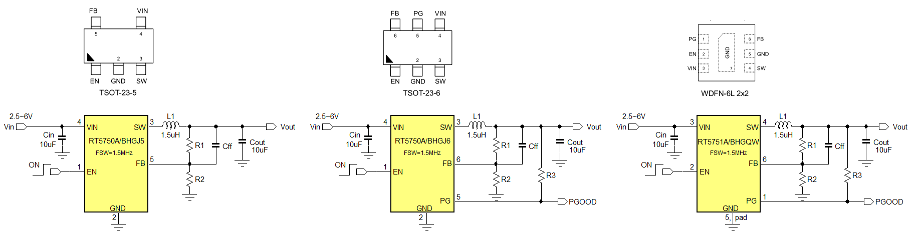
Figure 1
RT5750A/BHGJ5, RT5750A/BHGJ6 and RT5751A/BHGQW are compatible with multiple other semiconductor manufacturer solutions. Please contact your nearest Richtek sales office for more information.
Figure 2 shows the 1A ACOT RT5760 parts with the SOT563 package pinouts. These parts run at 2.2MHz, so external components can be smaller size. Some second source parts have pin 6 connected to Vout. In this case, RT5760C/DHGH6F can be used, since pin 6 is not connected. “A & C” versions have PSM mode, while “B & D” versions are Force-PWM.
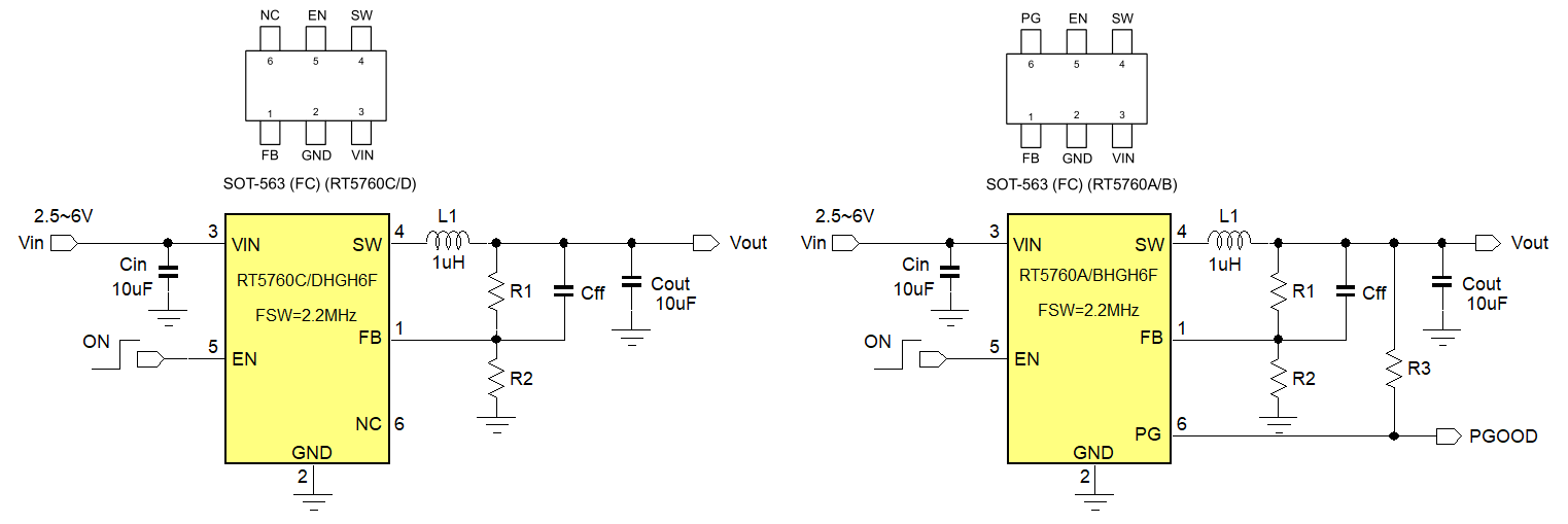
Figure 2
RT5760C/DHGH6F and RT5760A/BHGH6F are compatible with multiple other semiconductor manufacturer solutions. Please contact your nearest Richtek sales office for more information.
2.3. Low voltage buck IC up to
2A
The 2A ACOT parts shown in figure 3 are RT5752A/BHGJ5, RT5752A/BHGJ6 and RT5752A/BHGQW, they operate at 1.2MHz frequency. “A” versions have PSM mode, while “B” versions are Force-PWM.
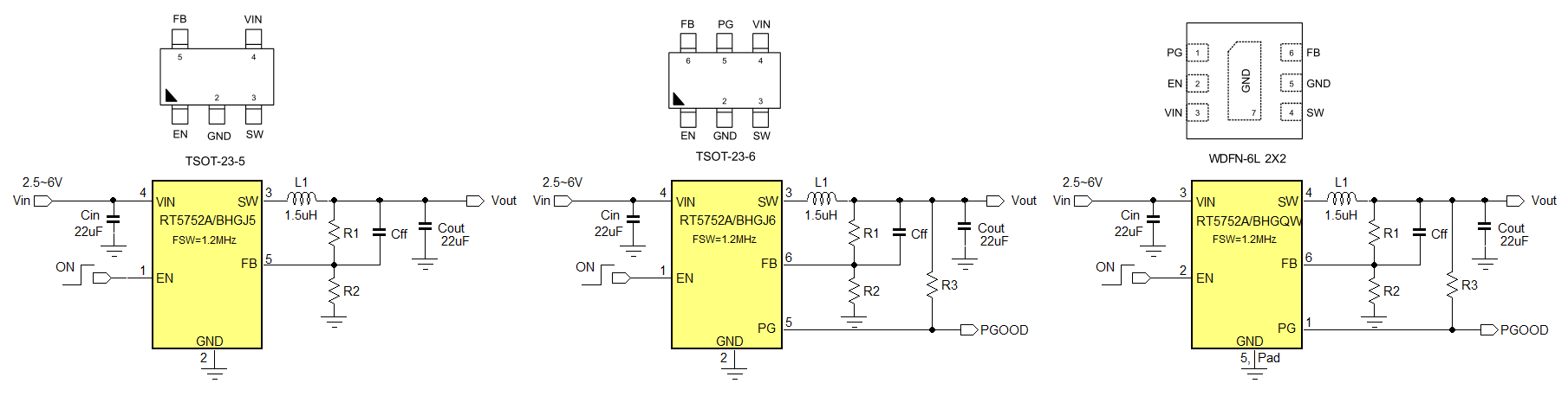
Figure 3
RT5752A/BHGJ6 and RT5752A/BHGQW (Pin 1 = NC) are compatible with multiple other semiconductor manufacturer solutions. Please contact your nearest Richtek sales office for more information.
Figure 4 shows the 2A ACOT RT5762 parts with the SOT563 package pinouts. These parts run at 1.2MHz. Some second source parts have pin 6 connected to Vout. In this case, RT5762C/DHGH6F can be used, since pin 6 is not connected. “A & C” versions have PSM mode, while “B & D” versions are Force-PWM.
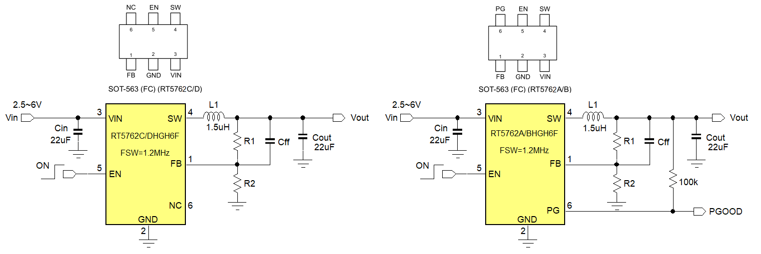
Figure 4
RT5762C/DHGH6F and RT5762A/BHGH6F are compatible with multiple other semiconductor manufacturer solutions. Please contact your nearest Richtek sales office for more information.
3.
17V/18V rated Buck converters
17V or 18V rated buck converters are normally used to convert a 12V rail into lower voltages like 5V, 3.3V or very voltages like 1.2V or 1.0V for powering SoC core voltages. Current levels can vary considerably but most common are 1A ~ 4A range.
In this range the (T)SOT23-6 packages with Flip-Chip technology are often used.
Richtek has many parts for this segment, but for second source design, the new generation ACOT® Buck is very suitable because this family is quite flexible with respect to external component choices, and they offer very good transient performance and high efficiency, and the flip-chip packages have surprisingly good thermal performance.
3.1. External Component
considerations for ACOT® HV Buck
Feedback network
Similar to LV Buck, the feedback network impedance does not play a role in Richtek 17/18V HV ACOT converter stability; it works well at both low and high feedback network impedance. The feed-forward capacitor Cff should be reserved, as it will be needed in some cases. With large values for Cff (>100pF) a resistor RT (~10kΩ) may be added between the feedback network and the FB pin, (see figure 5). This helps to reduce noise coupling to the FB pin, which in some noisy layouts can result in worse load regulation. It can be tested by applying a pulse load in CCM mode and check the output voltage for droop. (Other vendor COT topology devices can behave in similar way, so reserving RT makes sense for those parts as well).
Please keep in mind that some vendor parts may use Current Mode control loop with internal compensation. For these cases, the feedback network impedance may need to be adjusted to set the converter control bandwidth. In some applications, the resistor RT may be used to set the control bandwidth. So also for this case, the layout should reserve the RT resistor. If the other vendor part control topology and FB reference voltage is the same, it is quite possible that the feedback resistors can be the same for both parts.
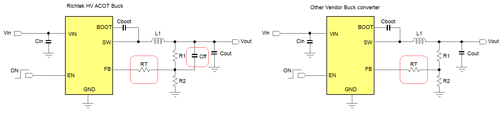
Figure 5
Inductor value
Generally, the inductor value is chosen based on a current ripple around 20~40% of the IC rated current according the formula:
Richtek HV ACOT® topology can accept a wide range inductor values. Smaller inductor values will improve the load transient performance. Larger inductor values reduce the output ripple, but worsen the transient response.
Output capacitance
The recommended output capacitance value in the datasheet will provide low ripple and good transient performance. Richtek HV ACOT® topology can also accept a wide range of output capacitors, but the use of the feed-forward capacitor Cff will be required for certain combinations to damp the loop response:
Larger output capacitance and Inductance values in combination with higher output voltage will require larger values for Cff. In the same way as LV Buck, HV ACOT® buck stability can be easily checked by applying a fast load step and observing the output voltage response: ringing in the step-load response means that the Cff value needs to be increased. See also: DC/DC Converter Testing with Fast Load Transient
Enable Pin
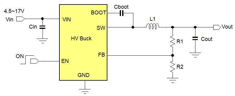
The Enable pin of the new generation Richtek HV ACOT® family can withstand high voltage and can be tied directly to VIN for automatic start-up. However, other vendor parts Enable pin may have lower voltage rating, and for these cases, the EN pin should be connected to Vin via a high value resistor. For common layout, it is therefore recommended to reserve a resistor to connect Enable pin to Vin for automatic start-up. See figure 6.
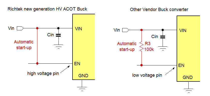
Figure 6
Bootstrap capacitor network
For HV buck the bootstrap capacitor will provide the voltage to switch-on the High-Side switching MOSFET. In many applications, a simple capacitor connected between BOOT pin and SW node will be sufficient. But in EMI critical applications, a resistor may be added in series with the bootstrap capacitor to reduce the switch-on speed of the high side MOSFET. Since the switching speed of parts from different suppliers will not be the same, it is recommended to reserve the series resistor in the bootstrap capacitor network as shown in figure 7, and the resistor can be used to tune the circuits for similar MOSFET switch-on speed.
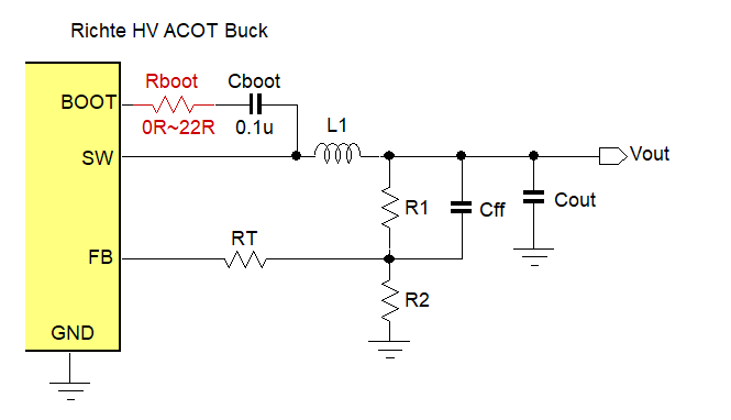
Figure 7
3.2. 17/18V voltage buck IC from
2A up to 4A in small packages
Figure 8 shows the new generation ACOT® 17V/18V rated 2A, 3A and 4A parts. The (T)SOT23-6 packages are most popular and several vendors provide the same pinout for these parts, making them very suitable for multi-source design. The SOT563 packages have smaller footprint, but have slightly worse thermal performance. All these parts have flip-chip package technology, which means that all IC pins are thermally connected to the silicon die, and therefore all pins can conduct heat from the die to the PCB. The “A” versions have PSM mode, while “B” versions are Force-PWM. Below application schematics are recommended for multiple source design with common PCB layout.
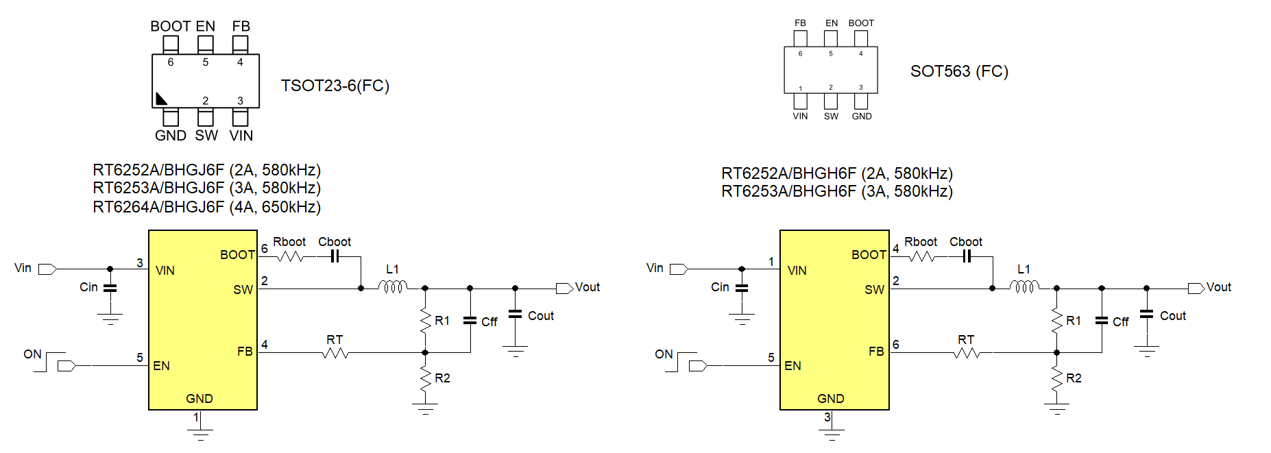
Figure 8
RT6252A/BHGJ6F, RT6253A/BHGJ6F, RT6252A/BHGH6F, RT6253A/BHGH6F and RT6264A/BHGJ6F are compatible with multiple other semiconductor manufacturer solutions. Please contact your nearest Richtek sales office for more information.
4.
24V/36V Low Current Buck Converters
Industrial applications often need to convert an unregulated 12V or 24V supply into lower voltage low power rails, for example to power a small MCU or sensor. For such cases, 24V rated or 36V rated Buck converter parts are used.
Although newer synchronous parts are available for this input voltage range, the asynchronous parts are still quite popular as the external Schottky diode exhibits very low switching losses and at moderate current levels, the forward conduction losses of the Schottky diodes are almost the same as the synchronous low side MOSFET losses. Several vendors provide buck converter solutions in (T)SOT23-6 with the same pinout for this range.
4.1. External components for
24V/36V low current Buck converter
In higher input voltage applications, the application duty-cycle can have a wider range. Current Mode control topology works well for wide duty-cycle applications, so Current Mode with internal compensation is most often used in this segment. There are two configurations for these parts: The GM type error amplifier (figure 9 left) and the Opamp type error amplifier (figure 9 right).
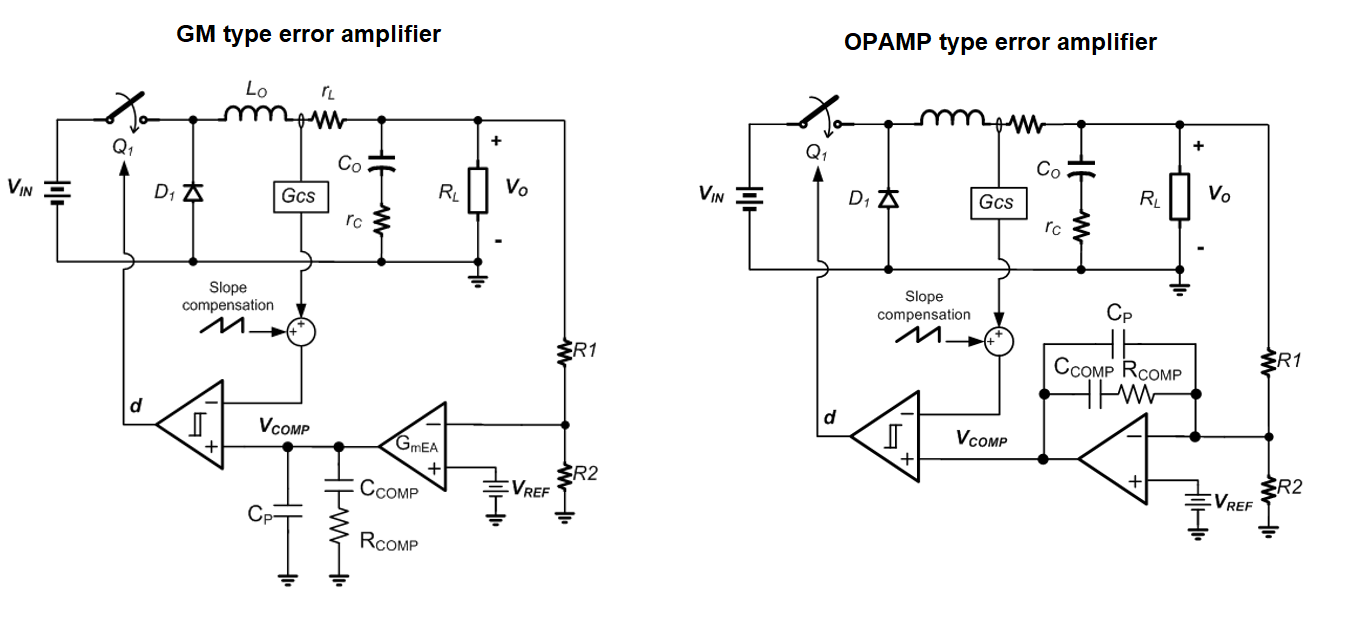
Figure 9
The GM type error amplifier compensation network is connected to IC ground. The error amplifier gain is fixed by the internal RCOMP resistor and therefore cannot be changed. The feedback network impedance does not play a role in the control loop gain, and can be freely chosen. This design has less flexibility in output capacitance values.
The Opamp type error amplifier compensation network is connected between error amplifier and the feedback pin. The error amplifier gain is now depending on internal RCOMP resistor and the external upper feedback resistor R1, and thus can be changed by changing the R1 value. It means that the feedback network impedance will play a role in the control loop gain, but this design allows more flexibility in output capacitor choice.
Feedback network
When designing the feedback network, it should first be checked which error amplifier configuration is used. For the Opamp type error amplifier, the control loop unity gain frequency FC is given by:
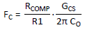
(RT8259 GCS = 2A/V, RT6200 GCS = 1.1A/V, FC ≈ 0.1*FSW)
The R1 value may need to be adjusted to set the unity gain frequency at the correct point (around 10% of the switching frequency) when using different output capacitance. In multi-source design, each source should be checked in this respect. For more information on Current Mode stability aspects, please see: DC/DC Converter Testing with Fast Load Transient
Some vendors recommend adding a feed-forward capacitor Cff in parallel with the upper feedback resistor to add some extra phase boost. The designer could reserve this component for multi-source design.
Inductor value
Generally, the inductor value for Current Mode converters is chosen based on a current ripple around 20~40% of the IC rated current according the formula:
Too small inductor values may lead to increased power loss and subharmonic switching due too small slope-comp / current ripple ratio. Too large inductor values may lead to poor phase margin due to due too large slope-comp / current ripple ratio.
Output capacitance
The output capacitance value will influence output voltage ripple, load transient sag/soar and converter crossover frequency. Especially the latter should be carefully checked. Too small output capacitance can lead to instability due to too high crossover frequency. For Opamp type error amp configurations, the feedback network impedance should be increased, to lower the error amplifier gain.
For GM type error amplifiers, the output capacitor value may need to stay within a certain range to maintain stability.
Schottky diode
For low current asynchronous Buck converters, the external Schottky diode selection is not very critical: The voltage rating should be higher than the maximum input voltage and the current rating is normally selected to be larger than the maximum load current.
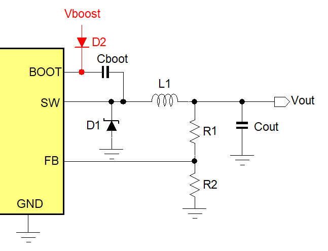
Figure 10
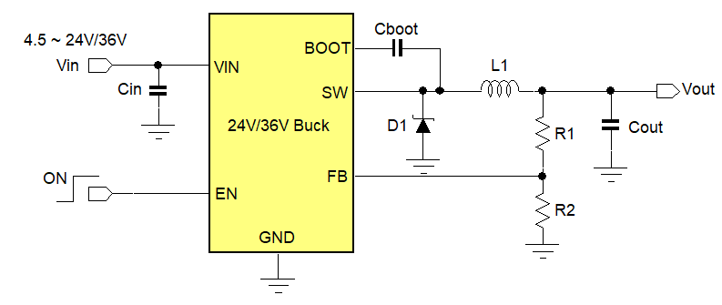
Bootstrap circuit
Some vendor devices require an external diode to supply a 3.3V ~ 5V supply to the bootstrap supply of the IC in order to drive the internal high-side MOSFET. For other vendors including Richtek, this external bootstrap supply (figure 10) is only recommended in case the switching duty-cycle can be larger than 65%. For applications that step down to 3.3V ~ 5V supply, the Vboost can be directly derived from the output voltage. For lower or higher voltage supplies, the Vboost can be derived from the input or output voltage via a zener clamp.
4.2. 24V/36V 1.2A and 0.6A
Current Mode Buck converter
Figure 11 shows the Richtek 24V and 36V rated parts for step down solutions at moderate current levels. The Richtek parts use Opamp type error amplifier and the compensator gain can be adjusted via the feedback network impedance. Cff and external bootstrap supply are normally not needed. For automatic start-up, the EN pin can be left floating. The below example schematic for 3.3V ~ 5V output can be used for multiple source design.
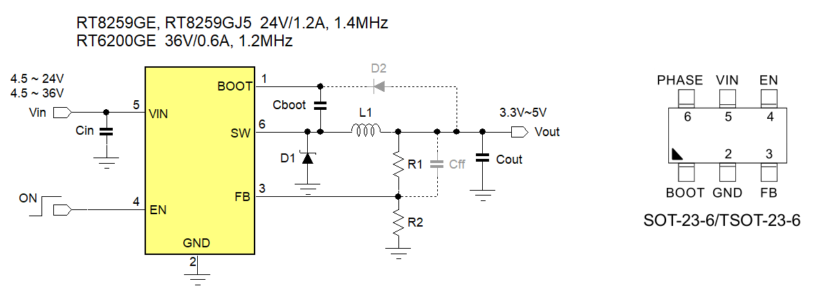
Figure 11
RT8259GE, RT8259GJ5 and RT6200GE are compatible with multiple semiconductor manufacturer solutions. Please contact your nearest Richtek sales office for more information.
5.
42V and 60V industrial & automotive buck
converters
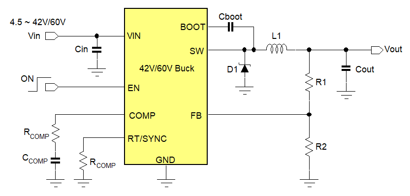
42V and 60V rated buck converters are often used in industrial and automotive applications, which dictate wide input voltage range, adjustable frequency, wide duty-cycle capability and packages with good thermal performance so they can operate at higher ambient temperatures. These parts often use a Current Mode control loop which can be synchronized to an external clock signal. External compensation is used in order to accommodate a wide range of output capacitors.
This higher voltage Buck converter segment is not covered by many power IC vendors, and finding pin compatible devices amongst different vendors is not that easy. We do see however that there is a need for 2nd sourcing in this segment as well, even automotive customers start to see the value of multi-source design in times of semiconductor shortage. To meet this need, Richtek has developed a family of 42V and 60V asynchronous buck converter devices with current ratings from 0.5A up to 5A, for consumer, industrial and automotive range, which are pin compatible with other IC vendor.
Table 1 shows the full range of parts for 42V and 60V rated buck converters.
|
Part number
|
Vin range
|
Current rating
|
Programmable Frequency range
|
External compensation
|
External soft-start
|
Power good
|
Spread Spectrum /AEC-Q100
|
Package
|
Pin compatible 2nd source?
|
|
Standard and Industrial range: RT63xx = Standard range, RTQ63xx = Industrial range, up to 42V input:
|
|
RT(Q)6340GSP
|
4.5 ~ 42V
|
0.5A
|
0.1 ~ 2.5MHz
|
Yes
|
No
|
No
|
No
|
PSOP-8
|
-
|
|
RT(Q)6340GQW
|
4.5 ~ 42V
|
0.5A
|
0.1 ~ 2.5MHz
|
Yes
|
Yes
|
Yes
|
No
|
DFN10L 3x3
|
Yes
|
|
RT(Q)6341GSP
|
4.5 ~ 42V
|
1.5A
|
0.1 ~ 2.5MHz
|
Yes
|
No
|
No
|
No
|
PSOP-8
|
-
|
|
RT(Q)6341GQW
|
4.5 ~ 42V
|
1.5A
|
0.1 ~ 2.5MHz
|
Yes
|
Yes
|
Yes
|
No
|
DFN10L 3x3
|
Yes
|
|
RT(Q)6342GSP
|
4.5 ~ 42V
|
2.5A
|
0.1 ~ 2.5MHz
|
Yes
|
No
|
No
|
No
|
PSOP-8
|
-
|
|
RT(Q)6342GQW
|
4.5 ~ 42V
|
2.5A
|
0.1 ~ 2.5MHz
|
Yes
|
Yes
|
Yes
|
No
|
DFN10L 3x3
|
Yes
|
|
RT(Q)6343GSP
|
4.5 ~ 42V
|
3.5A
|
0.1 ~ 2.5MHz
|
Yes
|
No
|
No
|
No
|
PSOP-8
|
Yes
|
|
RT(Q)6343GQW
|
4.5 ~ 42V
|
3.5A
|
0.1 ~ 2.5MHz
|
Yes
|
Yes
|
Yes
|
No
|
DFN10L 4x4
|
Yes
|
|
RT(Q)6345GSP
|
4.5 ~ 42V
|
5A
|
0.1 ~ 2.5MHz
|
Yes
|
No
|
No
|
No
|
PSOP-8
|
Yes
|
|
RT(Q)6345GQW
|
4.5 ~ 42V
|
5A
|
0.1 ~ 2.5MHz
|
Yes
|
Yes
|
Yes
|
No
|
DFN10L 4x4
|
Yes
|
|
Standard and Industrial range: RT63xx = Standard range, RTQ63xx = Industrial range, up to 60V input:
|
|
RT(Q)6360GSP
|
4.5 ~ 60V
|
0.5A
|
0.1 ~ 2.5MHz
|
Yes
|
No
|
No
|
No
|
PSOP-8
|
-
|
|
RT(Q)6360GQW
|
4.5 ~ 60V
|
0.5A
|
0.1 ~ 2.5MHz
|
Yes
|
Yes
|
Yes
|
No
|
DFN10L 3x3
|
Yes
|
|
RT(Q)6361GSP
|
4.5 ~ 60V
|
1.5A
|
0.1 ~ 2.5MHz
|
Yes
|
No
|
No
|
No
|
PSOP-8
|
-
|
|
RT(Q)6361GQW
|
4.5 ~ 60V
|
1.5A
|
0.1 ~ 2.5MHz
|
Yes
|
Yes
|
Yes
|
No
|
DFN10L 3x3
|
Yes
|
|
RT6362GFP
|
4.5 ~ 60V
|
2.5A
|
0.1 ~ 2.5MHz
|
Yes
|
Yes
|
Yes
|
No
|
MSOP-10
|
Yes
|
|
RT(Q)6362GSP
|
4.5 ~ 60V
|
2.5A
|
0.1 ~ 2.5MHz
|
Yes
|
No
|
No
|
No
|
PSOP-8
|
-
|
|
RT(Q)6362GQW
|
4.5 ~ 60V
|
2.5A
|
0.1 ~ 2.5MHz
|
Yes
|
Yes
|
Yes
|
No
|
DFN10L 3x3
|
Yes
|
|
RT(Q)6363GSP
|
4.5 ~ 60V
|
3.5A
|
0.1 ~ 2.5MHz
|
Yes
|
No
|
No
|
No
|
PSOP-8
|
Yes
|
|
RT(Q)6363GQW
|
4.5 ~ 60V
|
3.5A
|
0.1 ~ 2.5MHz
|
Yes
|
Yes
|
Yes
|
No
|
DFN10L 4x4
|
Yes
|
|
RT(Q)6365GSP
|
4.5 ~ 60V
|
5A
|
0.1 ~ 2.5MHz
|
Yes
|
No
|
No
|
No
|
PSOP-8
|
Yes
|
|
RT(Q)6365GQW
|
4.5 ~ 60V
|
5A
|
0.1 ~ 2.5MHz
|
Yes
|
Yes
|
Yes
|
No
|
DFN10L 4x4
|
Yes
|
|
Automotive Qualified AEC-Q100 range up to 42V input:
|
|
RTQ2940GSP
|
4.5 ~ 42V
|
0.5A
|
0.1 ~ 2.5MHz
|
Yes
|
No
|
No
|
Yes
|
PSOP-8
|
-
|
|
RTQ2940GQW
|
4.5 ~ 42V
|
0.5A
|
0.1 ~ 2.5MHz
|
Yes
|
Yes
|
Yes
|
Yes
|
DFN10L 3x3
|
Yes
|
|
RTQ2941GSP
|
4.5 ~ 42V
|
1.5A
|
0.1 ~ 2.5MHz
|
Yes
|
No
|
No
|
Yes
|
PSOP-8
|
-
|
|
RTQ2941GQW
|
4.5 ~ 42V
|
1.5A
|
0.1 ~ 2.5MHz
|
Yes
|
Yes
|
Yes
|
Yes
|
DFN10L 3x3
|
Yes
|
|
RTQ2942GSP
|
4.5 ~ 42V
|
2.5A
|
0.1 ~ 2.5MHz
|
Yes
|
No
|
No
|
Yes
|
PSOP-8
|
-
|
|
RTQ2942GQW
|
4.5 ~ 42V
|
2.5A
|
0.1 ~ 2.5MHz
|
Yes
|
Yes
|
Yes
|
Yes
|
DFN10L 3x3
|
Yes
|
|
RTQ2949GSP
|
4.5 ~ 42V
|
3A
|
0.1 ~ 2.5MHz
|
Yes
|
No
|
No
|
Yes
|
PSOP-8
|
Yes
|
|
RTQ2949AGSP
|
4.5 ~ 42V
|
3A
|
0.1 ~ 2.5MHz
|
Yes
|
No
|
No
|
Yes
|
PSOP-8
|
Yes
|
|
RTQ2943GSP
|
4.5 ~ 42V
|
3.5A
|
0.1 ~ 2.5MHz
|
Yes
|
No
|
No
|
Yes
|
PSOP-8
|
Yes
|
|
RTQ2943GQW
|
4.5 ~ 42V
|
3.5A
|
0.1 ~ 2.5MHz
|
Yes
|
Yes
|
Yes
|
Yes
|
DFN10L 4x4
|
-
|
|
RTQ2945GSP
|
4.5 ~ 42V
|
5A
|
0.1 ~ 2.5MHz
|
Yes
|
No
|
No
|
Yes
|
PSOP-8
|
Yes
|
|
RTQ2945GQW
|
4.5 ~ 42V
|
5A
|
0.1 ~ 2.5MHz
|
Yes
|
Yes
|
Yes
|
Yes
|
DFN10L 4x4
|
-
|
|
RTQ2945AGSP
|
4.5 ~ 42V
|
5A
|
0.1 ~ 2.5MHz
|
Yes
|
No
|
No
|
Yes
|
PSOP-8
|
Yes
|
|
Automotive Qualified AEC-Q100 range up to 60V input:
|
|
RTQ2960GSP
|
4.5 ~ 60V
|
0.5A
|
0.1 ~ 2.5MHz
|
Yes
|
No
|
No
|
Yes
|
PSOP-8
|
-
|
|
RTQ2960GQW
|
4.5 ~ 60V
|
0.5A
|
0.1 ~ 2.5MHz
|
Yes
|
Yes
|
Yes
|
Yes
|
DFN10L 3x3
|
Yes
|
|
RTQ2961GSP
|
4.5 ~ 60V
|
1.5A
|
0.1 ~ 2.5MHz
|
Yes
|
No
|
No
|
Yes
|
PSOP-8
|
-
|
|
RTQ2961GQW
|
4.5 ~ 60V
|
1.5A
|
0.1 ~ 2.5MHz
|
Yes
|
Yes
|
Yes
|
Yes
|
DFN10L 3x3
|
Yes
|
|
RTQ2962GSP
|
4.5 ~ 60V
|
2.5A
|
0.1 ~ 2.5MHz
|
Yes
|
No
|
No
|
Yes
|
PSOP-8
|
-
|
|
RTQ2962GQW
|
4.5 ~ 60V
|
2.5A
|
0.1 ~ 2.5MHz
|
Yes
|
Yes
|
Yes
|
Yes
|
DFN10L 3x3
|
Yes
|
|
RTQ2963GSP
|
4.5 ~ 60V
|
3.5A
|
0.1 ~ 2.5MHz
|
Yes
|
No
|
No
|
Yes
|
PSOP-8
|
Yes
|
|
RTQ2963GQW
|
4.5 ~ 60V
|
3.5A
|
0.1 ~ 2.5MHz
|
Yes
|
Yes
|
Yes
|
Yes
|
DFN10L 4x4
|
-
|
|
RTQ2965GSP
|
4.5 ~ 60V
|
5A
|
0.1 ~ 2.5MHz
|
Yes
|
No
|
No
|
Yes
|
PSOP-8
|
Yes
|
|
RTQ2965GQW
|
4.5 ~ 60V
|
5A
|
0.1 ~ 2.5MHz
|
Yes
|
Yes
|
Yes
|
Yes
|
DFN10L 4x4
|
-
|
Table 1
For a full list of 2nd source part numbers, please contact your nearest Richtek sales office or representative.
For application related information, please see Application Note AN063.
Which packages for pin compatible 2nd source?
As can be seen from table 1, the 0.5A 1.5A and 2.5A parts in DFN10L-3x3 package have a pin compatible 2nd source. For the 3.5A and 5A parts, there are pin compatible 2nd source for the PSOP-8 and DFN10L-4x4 packages. For one 60V / 2.5A part, RT6362GFP in MSOP-10 there is also a P2P 2nd source part. Figure 12 shows the different packages and application schematics that can be used for multi-source design.
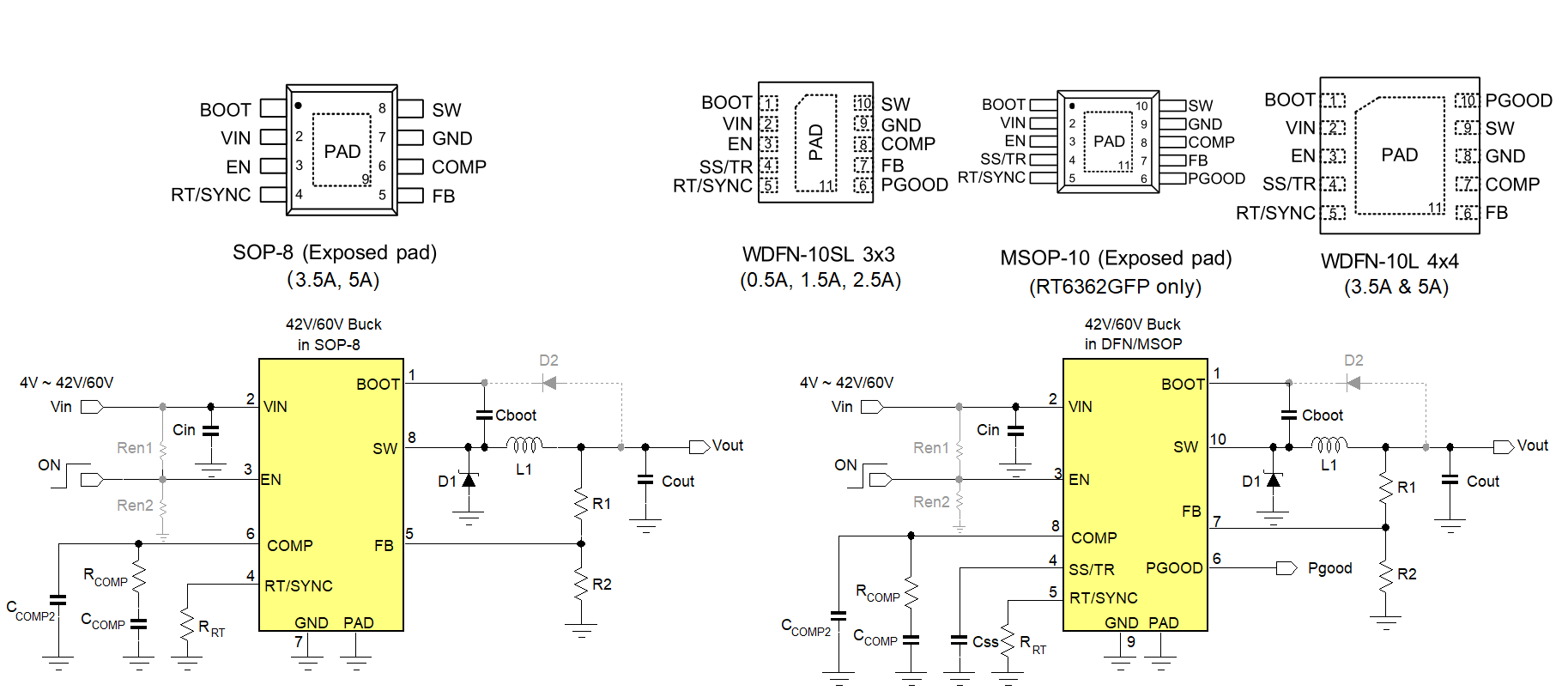
Figure 12
Design for automotive applications can be quite demanding. The Richtek RTQ29xx family has special features for automotive design, like close to 100% duty-cycle operation, smooth transition from normal to drop-out mode, and spread spectrum frequency jitter for reducing EMI radiation. The parts have been tested in various automotive applications and can be used successfully used as 2nd source, in many cases without the need of external component changes.
6.
Linear Regulators
6.1. Low voltage, low power
LDOs
Small low voltage linear regulators are often used to step down from a 5V rail to 3.3V 2.5V or 1.8V at low current levels. For low voltage, low power cases, a (T)SOT23 package is generally used. TSOT23 has reduced height, but has the same footprint as SOT23.
Which package pinout?
The 5-pin SOT23-5 or TSOT25-5 pinout as shown in figure 13 is very popular and is used by several semiconductor suppliers. The Richtek parts shown are RT9078 (300mA) and RT9080 (600mA).
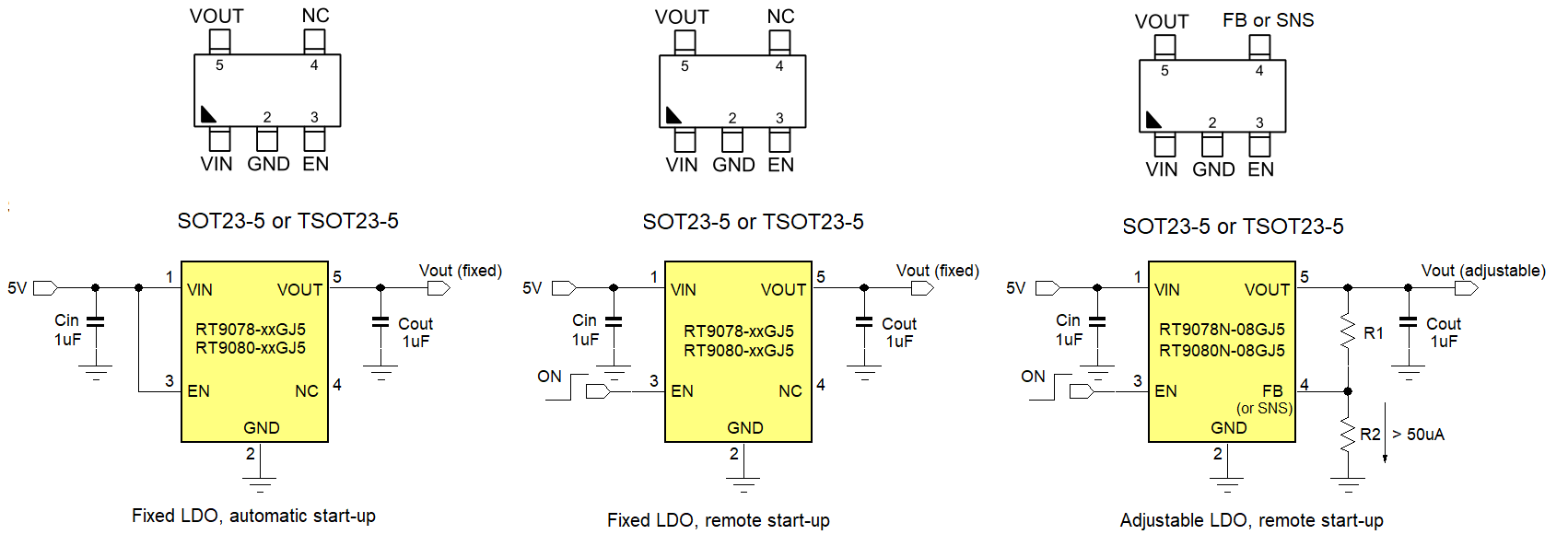
Figure 13
RT9078-xxGJ5/RT9080-xxGJ5 and RT9078N-08GJ5/RT9080N-08GJ5 are compatible with multiple semiconductor manufacturer solutions. Please contact your nearest Richtek sales office for more information.
This package/pinout also offers high flexibility: The Enable pin allows remote start-up / shut-down, but by tying the enable pin to VIN will give automatic start-up when the input voltage is applied. For fixed output voltage LDOs, pin 4 is left unconnected. These LDOs are also available in adjustable versions: Pin 4 now becomes the feedback or sense pin. By adding two feedback resistors, adjustable output voltage is achieved.
Fixed or Adjustable?
Of course, selecting a fixed LDO saves two resistors, but in times of shortage, some fixed voltage versions may not be readily available, while adjustable versions are quite common. Reserving the two resistors in the PCB layout will make the design more flexible for choosing parts that are more available. When choosing fixed voltage versions, it is wise to choose only popular values, like 3.3V, 2.5V, 1.8V, 1.5V or 1.2V, as these are more readily available among several suppliers.
Battery fed LDOs
One reason to choose fixed output voltage LDO’s would be for battery-fed applications, where the current in the feedback resistors would add too much battery drain. Fixed voltage, low Iq LDO’s with small footprint are more suitable here.
A popular package for these applications is the ZQFN1x1 (also called X2SON or SOT1194-1), which is available from at least three different vendors. Figure 14 shows the RT9073A 250mA low Iq LDO application.
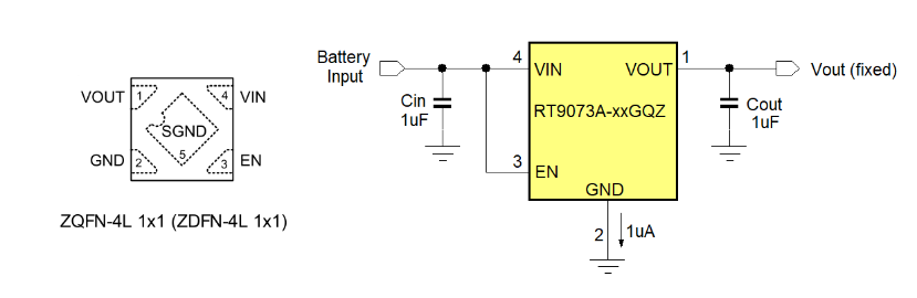
Figure 14
RT9073A-xxGQZ is compatible with multiple semiconductor manufacturer solutions. Please contact your nearest Richtek sales office for more information.
PSRR?
PSRR is an important parameter for LDO’s when noisy input rails need to be transformed in clean output voltages. Most of these low voltage LDO’s have decent PSRR around 70dB for low frequencies up to 10kHz. However, for removing noise of switch-mode pre-converters, very special high bandwidth LDOs are needed. These may be less easily available in times of shortage. A simple trick to reduce the HF switching noise is by placing a small bead in front of the LDO as shown in figure 15: The bead together with the LDO input capacitor form a high frequency low pass filter for switching noise, allowing the use of normal LDOs instead.
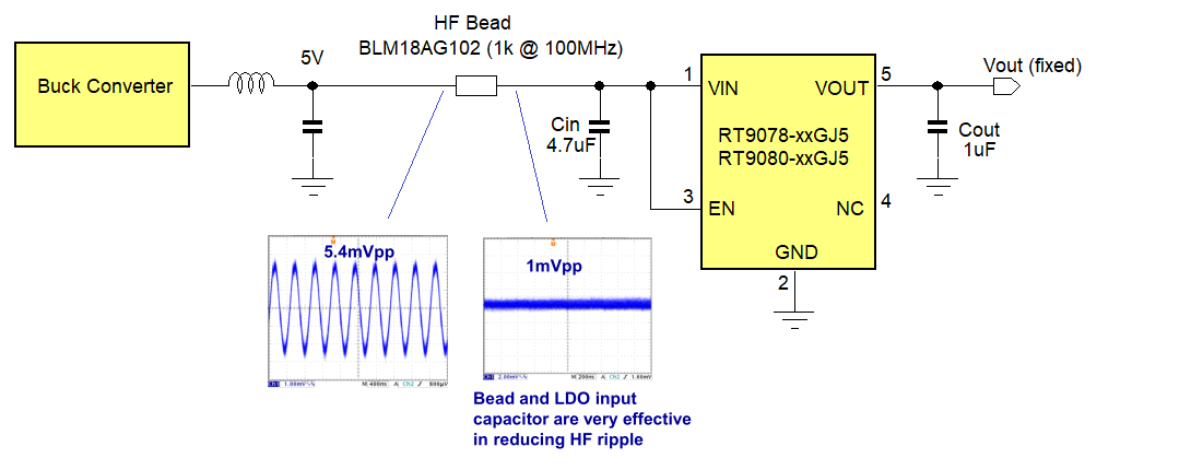
Figure 15
6.2. Medium voltage low power LDOs
LDOs with input voltage up to 36V are quite often used in industrial applications, to provide a low power standby supply for MCU or sensors. In this range, SOT23-5 is still quite popular. Figure 16 shows RT9069, a 36V 200mA fixed voltage low Iq LDO with Enable pin in the package version that has several pin compatible second source. 3.3V and 5V are the most common output voltages for this fixed voltage part.
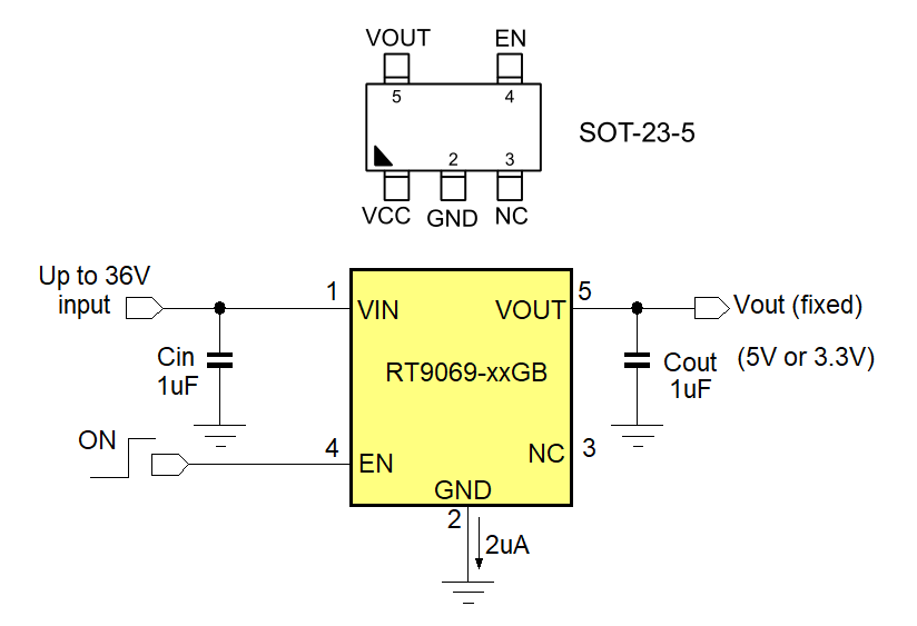
Figure 16
RT9069-xxGB is compatible with multiple semiconductor manufacturer solutions. Please contact your nearest Richtek sales office for more information.
As these higher voltage low current LDOs are often used as Always ON supply, three-pin package without Enable are also popular. Richtek’s RT9058-xxGV in SOT23-3 is a popular part, but the pinout is not the same as other competitor parts.
However, the layout can easily be adopted to accept two different footprints, as is shown in figure 17.
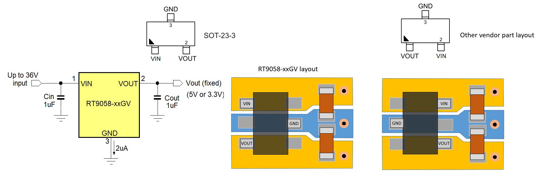
Figure 17
RT9058-xxGV can be used in combined footprint layout with multiple semiconductor manufacturer solutions. Please contact your nearest Richtek sales office for more information.
6.3. High voltage low power
LDOs
Some applications like industrial supplies that run from 48V rails need higher input voltage LDO’s. Richtek RT9068 is a popular 60V 50mA LDO. It comes in adjustable and fixed voltage versions, and the SOP-8 package with exposed pad (also called SOIC) is the most popular package, which also has good thermal properties. Figure 18 shows the RT9068 in the fixed and adjustable application with the SOP-8 package.
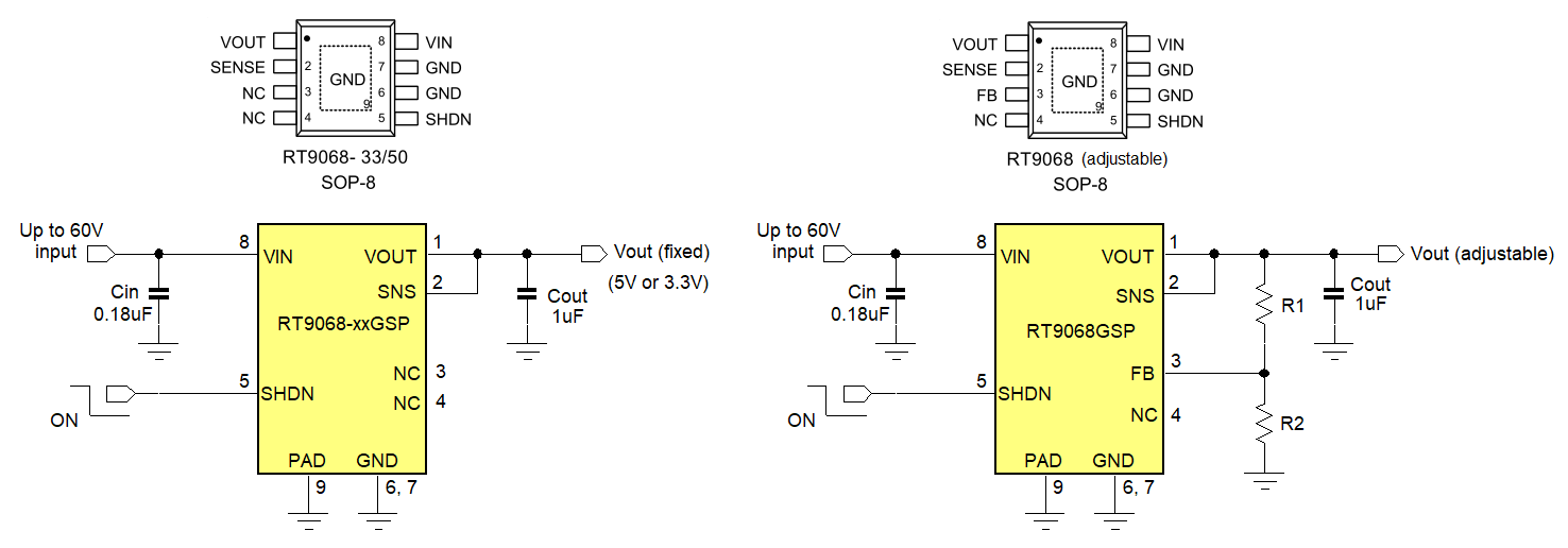
Figure 18
However, there are not so many 60V LDOs in the market, and it is hard to find parts that have pin compatible 2nd sources. For above parts, it is necessary to reserve another package / pinout in the same PCB layout. Things to consider: Check the enable/shutdown polarity: RT9068 SHDN pin is low to enable the device, but other vendor LDOs can be opposite. Output capacitor ESR: RT9068 is stable with low ESR ceramic capacitors (effective capacitance ≥ 1µF). Other vendor parts may need output capacitors with some ESR to be stable.
Feedback network: It is wise to reserve the feedback network for adjustable option. Other vendor LDOs may need a feed-forward capacitor in parallel with R1 for stability, so this could be reserved as well.
Package dissipation: SOP-8 with exposed pad can dissipate around 1W up to 60oC ambient in a good multilayer layout with thermal vias to other layers. Smaller packages may be worse in this respect.
7.
Summary
For general purpose power management parts like Buck converters and LDOs, it is quite possible to select components from different IC vendors that can be used in the same layout and sometimes even without any other component changes. The designer however must check different IC vendors for finding comparable parts. This application note has shown that some control topologies and package versions are easier than others for making a multi-source design. Besides its own package technology and IC pinouts, Richtek has also tried to make pin compatible parts to allow easy multi-source design, helping customers to find back-up solutions to reduce their logistic risks in times of shortages.
Besides the Buck converter and LDO multi-source solutions as described in this application note, Richtek also has multi-source pin compatible parts for Buck-boost converters, USB power switches, DDR terminators, Battery chargers and more. You can use the Cross Reference Tool on the Richtek website to enter your IC vendor part and see if there is a pin compatible Richtek part. Of course, you can also contact your local Richtek sales office or representative when choosing components for your multi-source power design.