Purpose
The RT4531 is an highly efficient,dual-channel white-LED driver designed for LCD display backlighting. The device can power up to 10 series LEDs at up to 20mA per string. It could be power source for smart phone and tablet Backlighting.
Introduction
General Product Information
The RT4531 is a dual-channel current source with high efficiency asynchronous boost converter for backlight application. The RT4531 has built-in 1.5A/36V power MOSFET and two high current-matching capability current sink, so RT4531 can drives up 10s2p white LED. The RT4531 can allow very low voltage headroom control, therefore to improve LED strings efficiency effectively. The RT4531 supports both PWM dimming and 1-wire digital dimming interface and it can realize 10 bit brightness code programming.
Product Feature
- Input Voltage Range : 2.5V to 5.5V
- Internal Soft-Start, UVLO, OTP, OCP, OVP
- Typical Shutdown Current : < 1μA
- 1MHz Switching Frequency
- Drives Up to 10 WLEDs in Two Strings
- Independent PWM Dimming and 1-Wire Dimming Control
- PWM Dimming Frequency from 20k to 100kHz
- Up to 10 Bit Dimming Resolution
- LED Current Accuracy ± 2% (> 5mA)
- LED Current Matching ± 2% (> 5mA)
- Built-in IFB1/IFB2 pin OVP, Short Protection, and Un-Use Detection
Key Performance Summary Table
|
Key Features
|
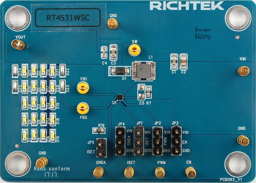
Evaluation Board Number : PCB093_V1
|
|
Default Input Voltage
|
2.5V to 5.5V
|
|
Max Output Current
|
20mA
|
|
Default Output Voltage
|
31V
|
|
Default Marking & Package Type
|
RT4531WSC, WL-CSP1.35x1.35-9(BSC)
|
|
Operation Frequency
|
Steady 1MHz at all loads
|
|
Protection
|
UVLO, OVP, OCP, Thermal Shutdown
|
Bench Test Setup Conditions
Headers Description and Placement
Carefully inspect all the components used in the EVB according to the following Bill of Materials table, and then make sure all the components are undamaged and correctly installed. If there is any missing or damaged component, which may occur during transportation, please contact our distributors or e-mail us at evb_service@richtek.com.
Test Points
The EVB is provided with the test points and pin names listed in the table below.
|
Pin Name
|
Pin No.
|
Comment (expected waveforms or voltage levels on test points)
|
|
ISET
|
A1
|
Full-Scale LED Current Set Pin. Connecting a resistor to the pin programs the full-scale LED current.
|
|
IFB2
|
A2
|
Single Output 2 for Backlight LED.
|
|
IFB1
|
A3
|
Single Output 1 for Backlight LED.
|
|
PWM
|
B1
|
Enable Control, and PWM Dimming Signal Input.
|
|
AGND
|
B2
|
Analog Ground.
|
|
GND
|
B3
|
Power Ground.
|
|
EN
|
C1
|
Enable Control, and 1-Wire Dimming Signal Input.
|
|
VIN
|
C2
|
Supply Input Pin.
|
|
SW
|
C3
|
Switch Node of Boost Converter.
|
Power-up & Measurement Procedure
1. Apply 3.6V nominal input power supply (2.5V < VIN < 5.5V) to the VIN and GND terminals.
2. The EN voltage is pulled to logic high by internal circuit to enable operation. Drive EN high (>1.4V) to enable operation or low (<0.4V) to disable operation. Pull EN pin to High pin that make EN voltage equal to VIN.
3. There is a 2-pin header JP3 “EN” for enable control. To use a jumper at “H” option to tie EN test pin to input power VIN for enabling the device. Inversely, to use a jumper at “L” option to tie EN test pin and ground GND for disabling the device.
4. The JP2 is the PWM control pin.
5. The ILED setting supports PWM dimming as below.
Output ILED Setting
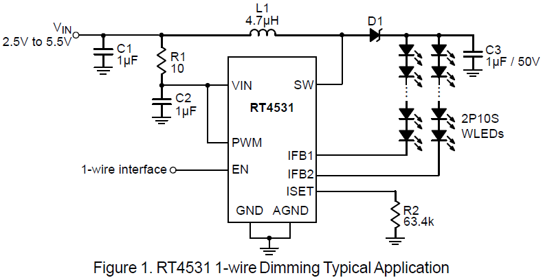
a. 1-wire Brightness Dimming
The RT4531 is built-in a 10-bit resolution brightness control. The EN pin features a simple 1-wire interface to allow digital brightness control. If the 1-wire dimming is needed, signals of a specific pattern should be input detection window into EN pin; Otherwise, PWM pin need to be enabled. (refer to Timing Diagram1 for Continuous Coding). The Register Program and register map give an overview of the protocol used by RT4531. By the 1-wire Brightness Dimming, a master can program the 10-bit code D1 (LSB) to D10 (MSB) to any of 1024 steps with a single command. The programmed value will be stored in an internal register and set the dual-channel current according to Equation 2. The code will be reset to default value when the IC is shut down or disabled.
 (2)
(2)
Where :
IFB : the full-scale LED current set by the RISET at ISET pin.
Code : the 10-bit DAC code D1 to D10 programmed by 1-wire interface.To enter 1-wire dimming mode, the following digital pattern on the EN pin must be recognized by the IC when the IC starts from the shutdown mode.
1. Pull the EN pin high to enable the RT4531 and start the detection window for digital dimming.
2. After the digital dimming detection delay time (T-es_delay, >300μs), drive the EN low for more than the detection time (T-es_det, >400μs).
3. Pull the EN pin high after the detection time (>400μs) and before the detection window (Tes_win, <1.23ms), once the above 3 conditions are met, the IC immediately enters the 1-wire dimming mode. The digital dimming communication can start before the detection window expires. Once the dimming mode is selected, it cannot be changed without another start up. This means the IC needs to be shut down by pulling the EN low for 2.5ms and restarts. See the dimming mode detection and softstart for a graphical explanation. (see Timing Diagram1 for 1-wire Continuous Coding).
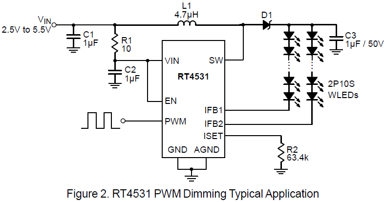
b. PWM Brightness Dimming
Besides programmable built-in 1-wire backlight LED current control, the RT4531 features a built-in PWM dimming current control by PWM pin, offering a linear current dimming by external clock source. In order to guarantee the PWM dimming resolution, recommending PWM dimming frequency have to be operated at range of 20kHz to 100kHz.When the PWM pin is constantly high, the dual channel current is regulated to full-scale according to Equation 1. The PWM pin allows PWM signals to reduce this regulation current according to the PWM duty cycle;therefore, it achieves LED brightness dimming. The relationship between the PWM duty cycle and IFBx current is given by Equation 3.
 (3)
(3)
Where :
IFBx is the current of each current sink, IFB is the fullscale LED current, Duty is the duty cycle information detected from the PWM signals.
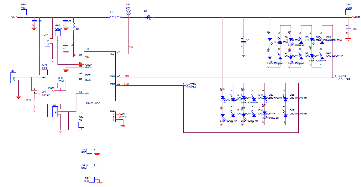
Schematic, Bill of Materials & Board Layout
EVB Schematic Diagram
Bill of Materials
|
Reference
|
Qty
|
Part Number
|
Description
|
Package
|
Manufacturer
|
|
U1
|
1
|
RT4531WSC
|
WLED Driver
|
WL-CSP-9B 1.35x1.35 (BSC)
|
RICHTEK
|
|
C1, C3
|
1
|
C1608X5R1E105K080AC
|
1μF/25V/X5R/0603
|
C-0603
|
TDK
|
|
C2
|
1
|
C2012X7R1H105KT000N
|
1μF/50V/X7R/0805
|
C-0805
|
TDK
|
|
D1
|
1
|
SS0540_T1
|
SS0540
|
D-1206
|
PANJIT
|
|
D2, D3, D4, D5, D6, D7, D8, D9, D10, D11, D12, D13, D14, D15, D16, D17, D18, D19, D20, D21
|
24
|
LNL-190UW-4H
|
白光LED
|
D-0603
|
光楠
|
|
D22, D23, D24, D25
|
4
|
|
SHORT
|
|
|
|
L1
|
1
|
NR4018T4R7M
|
4.7μH
|
L-SH4018
|
Taiyo Yuden
|
|
R19
|
1
|
RTT036342FTP
|
63.4k/0603/±1%
|
R-0603
|
旺詮
|
|
R7
|
1
|
WR06X10R0FTL
|
10Ω/0603/±1%
|
R-0603
|
WALSIN
|
PCB Layout
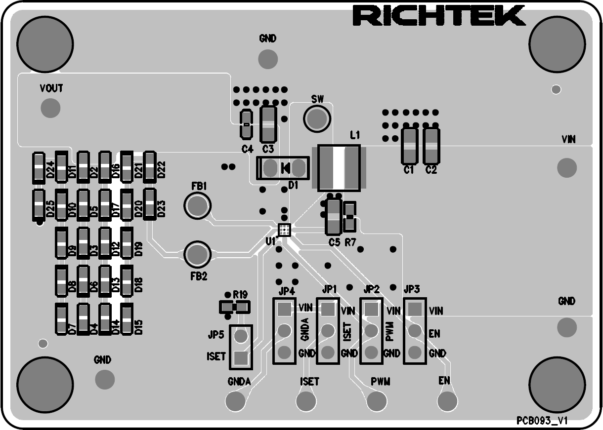
PCB Layout—Top View
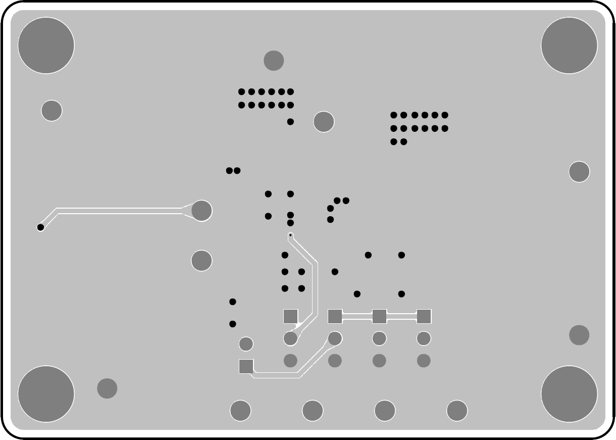
PCB Layout—Bottom Side