Selecting a Step-down (Buck) Converter
Step-down (Buck) Converters
Buck converters are switch-mode step-down converters which can provide high efficiency and high flexibility at higher VIN/VOUT ratios and higher load current.
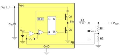
Most Buck converters contain an internal high side MOSFET and synchronous rectifier MOSFET, which are in turn switched on and off via internal duty-cycle control circuit to regulate the average output voltage. The switching waveform is filtered via an external LC filter stage.
Due to the fact that the MOSFETs are either ON or OFF, they dissipate very little power, and the duty-cycle control makes large VIN/VOUT ratios possible. The internal MOSFETs RDS(ON) mainly determines the current handling capabilities of the Buck converter, and the MOSFET voltage ratings determine the maximum input voltage. The switching frequency together with the external LC filter components will determine the ripple voltage on the output.
Higher switching frequency buck converters can use smaller filter components, but switch losses will increase. Buck converters with Pulse Skipping Mode (PSM) will reduce their switching frequency at light load, thereby increasing light load efficiency, which can be important in applications with low power standby modes. Special Buck topologies like ACOT™ have very fast loop response and are very suitable for applications that exhibit very fast load transients, like DDR, Core SoC, FPGA and ASIC supplies.
You might be interested in...
- Feature Product
- Application Notes
- ACOT™ Design Tools
- Richtek Designer™ allows you run simulations on a wide range of Buck converters.
- Parametric Search: Get your design started in no time!
