1. Introduction
The USB Type-C standard has been developed to meet
the ever growing needs of connectivity between modern devices. USB Type-C
connectivity provides both power and data exchange at higher power levels
and higher speeds compared to the legacy USB standard. The mechanical design
of the USB Type-C connector and receptacle has also been improved, to enable
smaller form factor and make the connection more user-friendly.
Table 1 below shows a comparison between the older
USB and new USB Type-C standard :
|
Connector
Picture
|
Connections
|
Data Speed
|
Voltage/Current
|
|
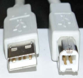
USB 1.x/2.0
standard
|
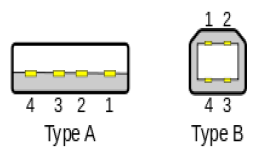
1 = VBUS, 4 = GND
3 = Data+, 2 = Data-
|
USB 1.0/1.1 :
Low speed : 1.5Mbps
Full speed : 12Mbps
USB 2.0 :
High speed : 480Mbps
|
5V/500mA
BC1.2 : 5V/1.5A
(for charging systems)
|
|
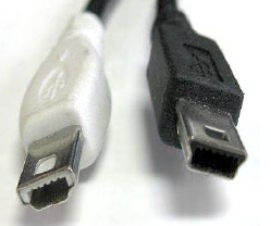
USB 1.x/2.0 Mini
|
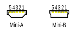
1 = VBUS, 5 = GND
3 = Data+, 2 = Data-
4 = ID pin :
Host = GND, device = float
|
|
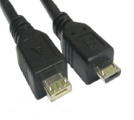
USB 1.x/2.0
Micro
|
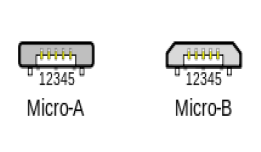
1 = VBUS, 5 = GND
3 = Data+, 2 = Data-
4 = ID pin :
Host = GND, device = float
|
|
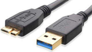
USB 3.0
|
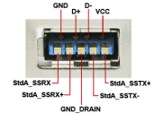 
1 = VBUS, 5, 8 = GND
2 = Data-, 3 = Data+
4 = USB-OTG,
6 = Tx-, 7 = Tx+, 9 = Rx-, 10 = Rx+
|
USB 3.0 :
Super speed: 5Gbps
|
5V/900mA
|
|
USB Type-C :
Smaller physical size
Reversible plug
Higher voltage & current
Auto-configurable
Highest data speed
|
Receptacle :
Plug:
Legacy Data-, Data+
Two pairs of Rx1/2 and Tx1/2
CC1/2 for configuration
VCONN (active cable power)
SBU 1/2 for sideband/audio
|
USB 2.0 :
High speed : 480Mbps
USB 3.0 :
Super speed : 5Gbps
USB 3.1 :
Super speed+ : 10Gbps
|
Default : 5V / 1.5A
5V/3A max
USB PD :
5V to 20V, 5A max
USB PD 3.0 with PPS
3V to 20V, 5A max
|
Table 1
From Table 1 it can be seen that the new USB Type-C
standard has several important advantages :
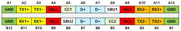
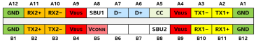
- USB Type-C plug is reversible, so it can be plugged in either way;
the pinning is laid out in such a way that power connections will always
meet correctly. Since the receptacle has two rows of D+ and D- where the
two D+ lines and the two D- lines are connected together so the D+ and
D- will always meet-up. The high speed TX lines and RX lines cannot be
connected together. Therefore the USB Type-C CC lines are used to
identify the cable orientation and will configure the TX/RX hardware to
work correctly.
Figure 1 : USB Type-C receptacle and cable plug
pinning.
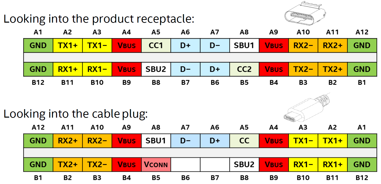
Figure 1
- Another difference between older USB standards and the new USB Type-C
standard is the dual role capability : USB Type-C cables have identical
plugs on either side of the cable, which means that devices connected
together have to tell each other who will be acting as host and who will
be acting as device. Note that these roles need to be determined for
both data and power after connection of the cable: For data
transmission, the host is called the Downstream Facing Port (DFP) and
the device is called the Upstream Facing Port (UFP). For power, the
power provider is the Source and power consumer is the Sink. Some
applications can have Dual Roles for Data (DRD) and Dual Role for Power
(DRP). The CC lines will be used to define the power role of the two
connected devices during connection.
- Another advantage of the USB Type-C system is its higher power
capability. Whereas the legacy USB was able to provide 2.5W only, USB
Type-C is able to provide up to 5V/3A, 15W max, and with Power Delivery,
the voltage & current range is increased to 20V/5A for maximum power of
100W. This makes it possible to power larger devices from the USB PD
port, like monitors, and also allows charging devices with large battery
packs like notebook computers. The new USB PD 3.0 standard also supports
Programmable Power Supply (PPS) which allows fine adjustment of the bus
voltage and current, and even allows lower voltage than 5V; PPS VBUS can
be adjusted down to 3V which is very useful in Direct Charge systems
where the Bus voltage is directly connected to the battery for highest
efficiency charging. Standard type-C cables are rated for currents up to
3A. For higher currents up to 5A, special E-marked cables need to be
used. These cables include a Cable ID IC that indentifies the cables
capability via the CC line. E-mark ICs require a 5V power supply to be
applied to the cable VCONN pin via one of the CC wires.
- The Super Speed + 10Gbps data rate via the TX/RX pairs makes it
possible to transfer signals that previously needed dedicated cables,
like HDMI/DisplayPort/Thunderbolt, and allows 4k video to be transferred
over USB Type-C. HDMI signal transfer via USB Type-C cables requires
special use of the data transfer pairs in the cable, which is called
Alternate Mode.
Below figures show some examples of USB Type-C
applications and related Richtek power management ICs :
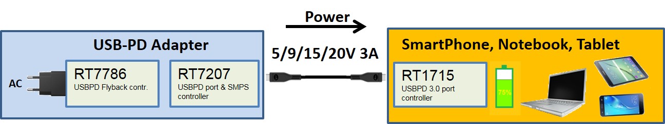
Figure 2.
Figure 2 shows a typical USB-PD adapter charging
solution, where the adapter power supply provides an adjustable USB bus
voltage 5V, 9V, 15V or 20V based on the request of the device attached.
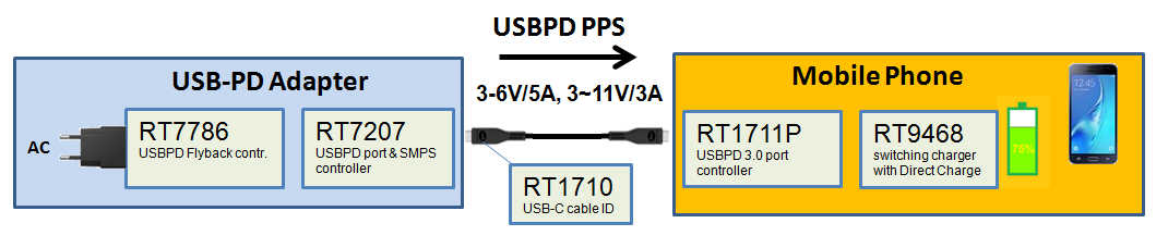
Figure 3
Figure 3 is a similar application as Figure 2, but now
utilizing the USBPD 3.0 Programmable Power Supply function to fine-adjust
the bus voltage over a wider voltage range. The extended VBUS low voltage
range down to 3V makes it possible to use the Direct Charge concept, which
connects the VBUS directly to the battery and controls the battery charge
current and voltage via the USB PD 3.0 communication protocol.
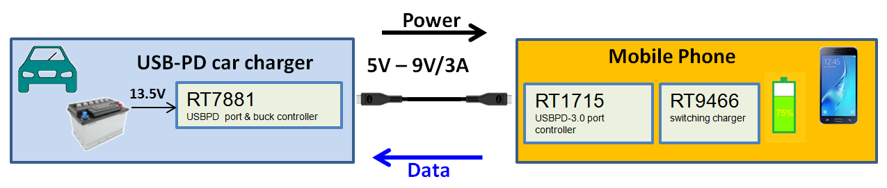
Figure 4
Figure 4 shows a car charger application where the car
battery voltage is stepped down to 5V or 9V based on the request of the
battery charger in the mobile phone. The mobile phone can provide data (like
audio) to the car infotainment system.
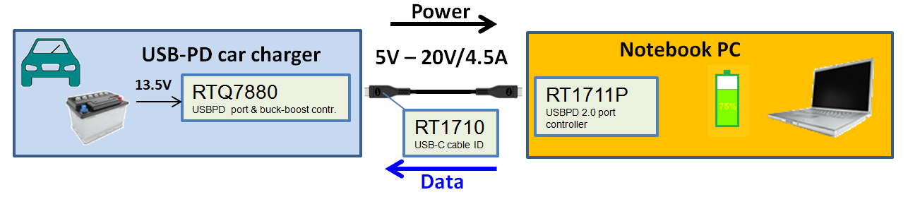
Figure 5
To charge larger devices like notebook computers from
the car battery, higher bus voltage is needed. Figure 5 shows a 90W car
charging solution which makes use of a buck-boost converter. Again the
notebook computer will request a suitable BUS voltage via the USB-PD
protocol. The higher 4.5A cable current will require the use of an active
cable with E-mark IC.
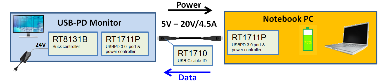
Figure 6
Computer Displays with USB Power Delivery can act as
power source as is shown in Figure 6 where a USB-PD monitor provides power
to the Notebook computer while receiving display data over the same USB
cable in Alternate Mode.
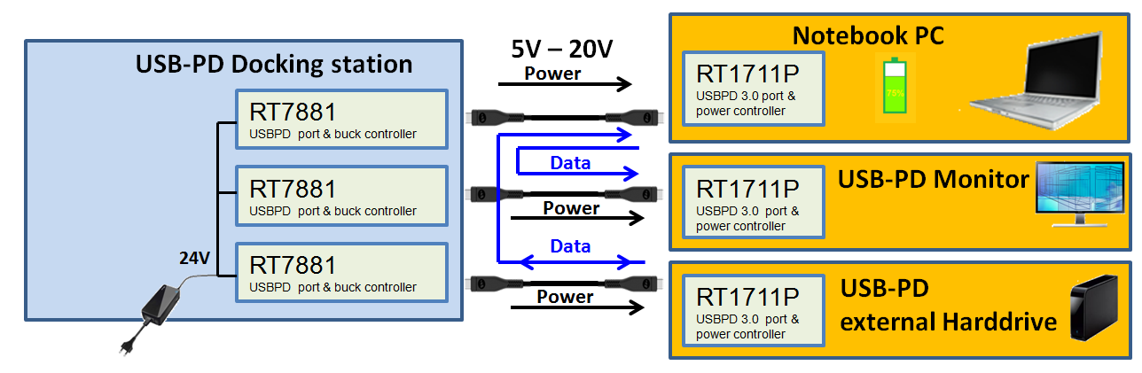
Figure 7
Figure 7 shows a powered docking station which can
connect to several devices, delivering power and routing data streams
between the devices.
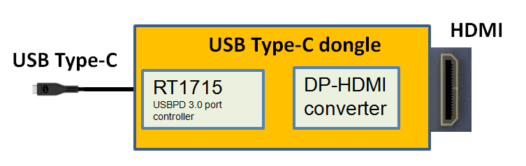
Figure 8
With the introduction of USB Type-C, there is a need
to be able to connect other interfaces to this port.
Figure 8 shows a USB Type-C to HDMI converter cable.
The bus voltage will stay at 5V, and the converter electronics are powered
from the bus voltage.
2. How USB Type-C configures data and power
Data transfer
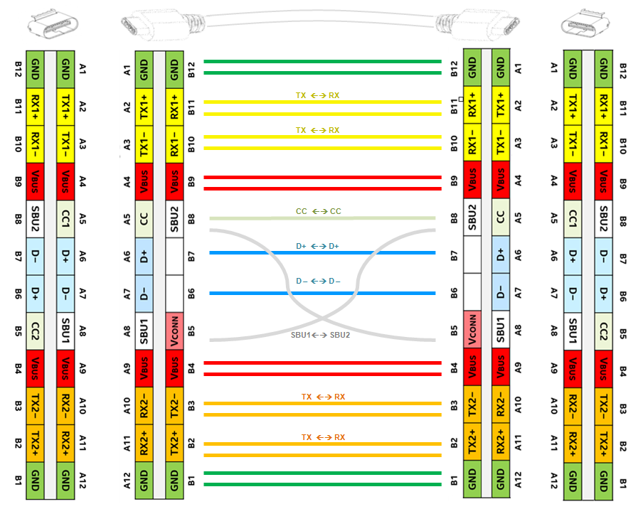
Figure 9 : non-twisted, non-flipped straight
connection.
Figure 9 shows a non-twisted cable with un-flipped
connector –receptacle position.
From left receptacle to right receptacle, the
RX1pair connects to TX1 pair and Rx2 pair connects to TX2 pair.
D+ connects to D+ and D- connects to D-. SBU1
connects to SBU2. CC1 connects via CC wire to CC1.
USB-3.1 uses only two data pairs. In this case, the
high speed data travels via RX1+/- and TX1+/- from one side to the other
side.
Note that VCONN is not wired through; the VCONN
voltage for powering cable E-mark ICs is only provided from one side, after
determining whether a cable includes an E-mark IC or not.
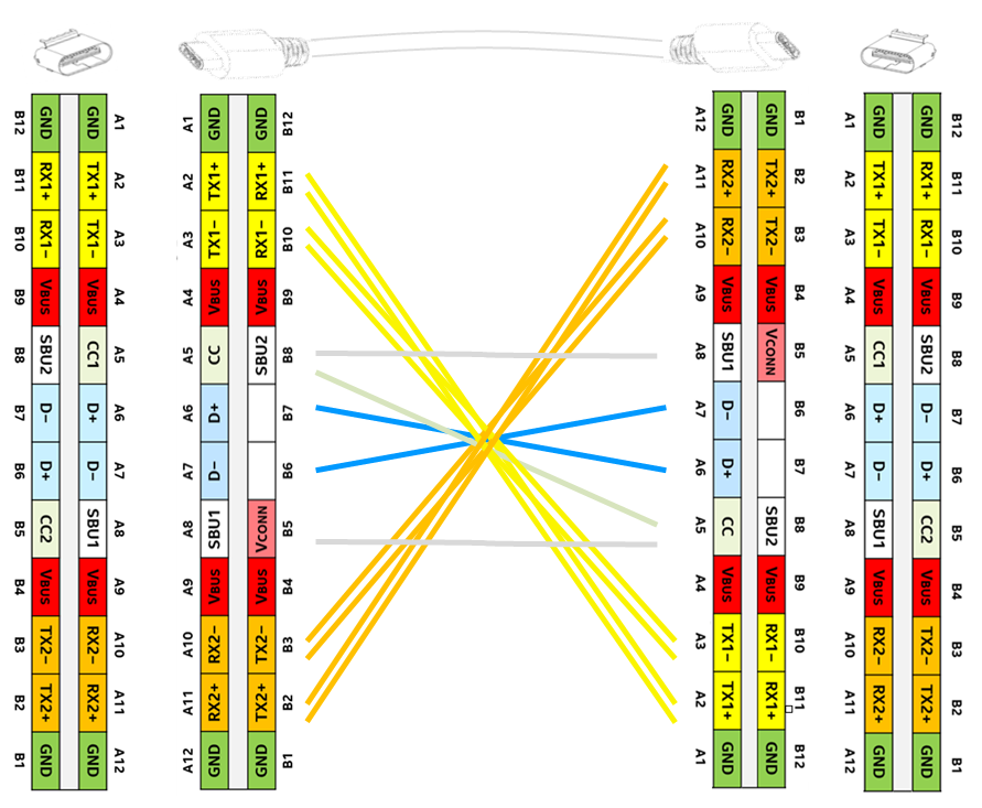
Figure 10 : twisted cable connection
Figure 10 shows a twisted cable connection with
receptacle in same position.
In this condition, from left receptacle to right
receptacle, the RX1 pair connects to TX2 pair and Rx2 pair connects to TX1
pair. D+ still connects to D+ and D- still connects to D-. SBU1 connects to
SBU1, SBU2 to SBU2. CC1 connects via CC wire to CC2. High speed data now
needs to travel from RX1+/- and TX1+/- left to RX2+/- and TX2+/- on the
right. It means the data transceiver needs to switch to different data
pairs.
There are totally 4 connection possibilities:
flipped or non flipped receptacle and twisted or non twisted cable.
In USB 3.1 systems, the RX/TX data-lines require a
multiplexer to correctly reconfigure the RX/TX lines in all possible cable
orientations. Figure 11 shows the data bus routing possibilities between to
USB Type-C ports. The cable / receptacle orientations are detected via the
CC1/CC2 pins on either side. The CC (Channel Configuration) logic controller
will set the multiplexer function accordingly. This can be done either via a
multiplexer switch or data line selection embedded in the USB chipset.
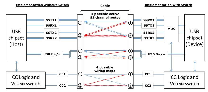
Figure 11
Power transfer
The basic USB Type-C Source to Sink without Power
Delivery block diagram is shown in Figure 12.
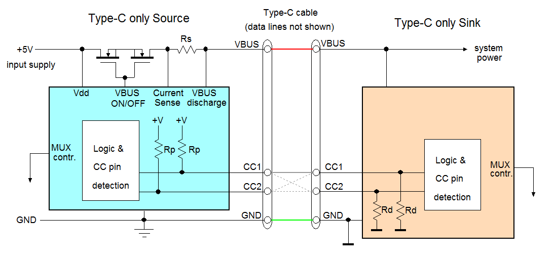
Figure 12
A USB Type-C source will always include a MOSFET
switch for enabling/disabling the VBUS voltage. It can also include a VBUS
current sense, to check for over-current conditions, and a VBUS discharge
function. Both Source and Sink will include a CC1/CC2 line detection
circuit.
The CC (Channel Configuration) lines are used to
establish power exchange between the two applications connected together.
Initially, the USB Type-C VBUS line will be unpowered. During the cable
connection the power role of each application needs to be defined. It is
defined that the power provider (source) will pull-up the CC lines at the
receptacle and the power consumer will pull down the CC lines at the
receptacle.
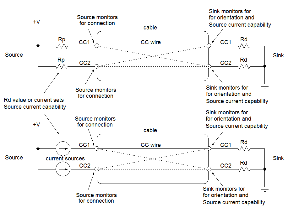
Figure 13
Figure 13 shows the method for establishing power
role, cable orientation and current capability: Source pulls up CC1 and CC2
with resistor Rp. It monitors the CC1/CC2 lines, which will be high when
nothing is connected. As soon as Sink is connected, it pulls the CC1 and CC2
lines down with resistor Rd. Since there is only one CC line in the cable,
the Source will see either CC1 or CC2 voltage dropping. The Sink also checks
the CC1/CC2 lines and checks the voltage of the line that is pulled up. The
voltage level will tell the Sink how much current the Source is able to
deliver. It is also possible to use current sources instead of pull-up
resistor Rp, which is easier to implement in ICs and makes the application
less sensitive to V+ tolerance.
The Sink pull-down resistor Rd is defined to be
5.1kΩ. The CC line voltage is now defined by the Source pull-up resistor Rp
values (or current source values). These are defined for 3 different Bus
current capabilities : The lowest voltage on the CC line (around 0.41V)
means default USB power (current = 500mA for USB2.0 or 900mA in USB3.0). A
higher CC line voltage (around 0.92V) defines a current capability of 1.5A.
When the CC line voltage is around 1.68V, the maximum current capability is
defined at 3A. See Figure 14.
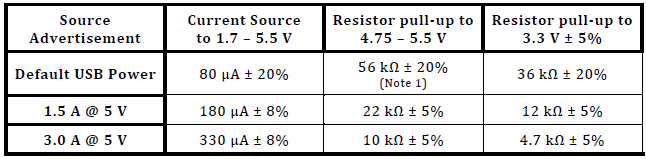
Figure 14
Figure 15 shows an example measurement where a power
provider (Source) is being connected to a power consumer (Sink) by means of
a normal USB Type-C cable.
|
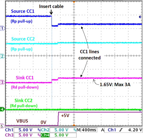
Figure 15
|
Initially the CC1 & CC2 pins of the
Source receptacle are pulled up via the two Rp resistors, and
the CC1 & CC2 pins of the Sink are pulled down via the Rd
resistors.
When the cable is connected, it depends
on cable orientation which CC1/2 signals will line-up. In this
case the cable was not twisted, and CC1 at Source connects to
CC1 at Sink, so the CC1 line now shows a voltage determined by
the Rp/Rd resistor divider. The voltage level is read by the
Sink so it knows how much current the Source is able to provide.
In this example, the connected CC1 line
shows around 1.65V, which means the Source is able to provide
maximum 3A current.
The 5V Bus voltage is enabled after the
CC line connection has been verified.
In USB Type-C only without Power
Delivery systems, the Rp/Rd divider will determine the maximum
bus current that can be delivered, but the source can only
provide 5V.
|
USB Type-C systems with Power Delivery (PD) can
increase the bus voltage, from 5V up to 20V maximum. The communication
between Source and Sink regarding bus voltage and current is then done via
serial BMC code on the connected CC line.
The basic USB Type-C Source to Sink with Power
Delivery block diagram is shown in Figure 16.
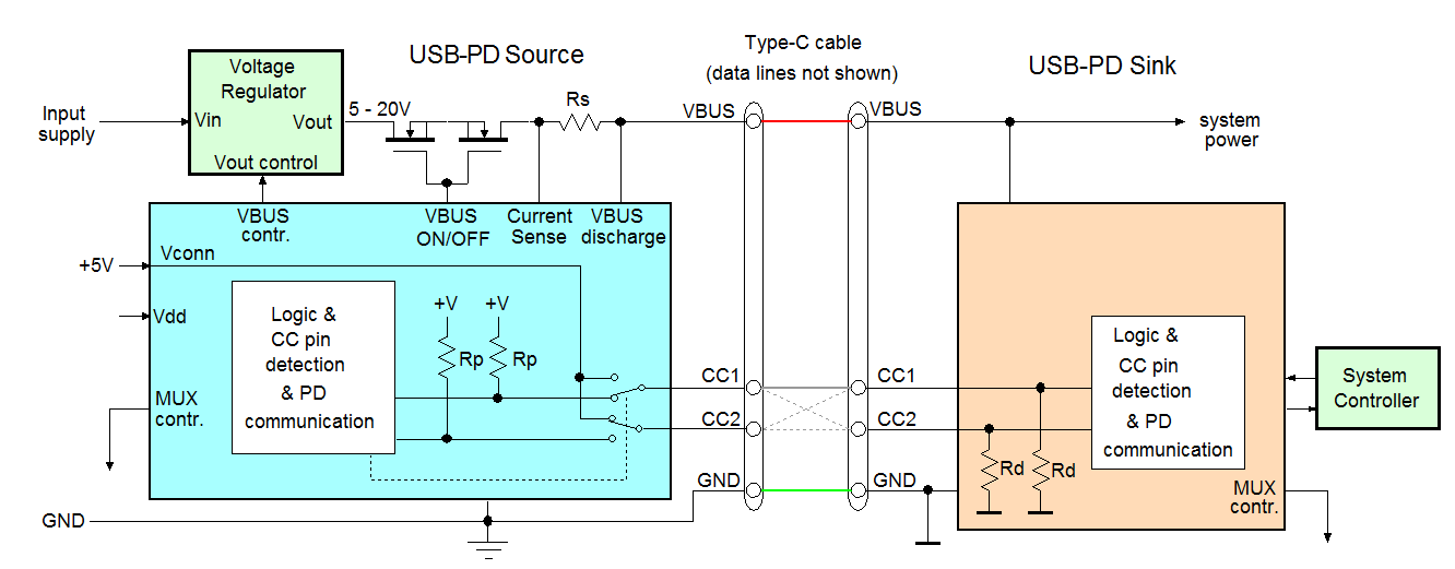
Figure 16
The Source now includes a voltage regulator that is
controlled by the Source PD controller. Depending on the input voltage and
the maximum bus voltage requirements, this voltage regulator can be a buck,
boost or buck-boost or a flyback converter. The CC line PD communication is
handled by the PD controller as well. USB-PD systems also need to be able to
switch a VCONN supply to one of the CC lines. (see later section on eMark
ICs).
After cable connection has been established, devices
with Power Delivery (PD) function will start SOP communication via the
active CC line regarding power profile selection: The Sink will interrogate
the Source regarding available power profiles (different bus voltages and
currents). Because the Sink power requests are often related to the Sink
system (i.e. battery charger), it is often the Sink embedded system
controller (EC) that will first communicate with the Sink PD controller (via
I2C) for specific power requests.
Figure 17 shows an example of a PD request where the
Sink requests a higher bus voltage.
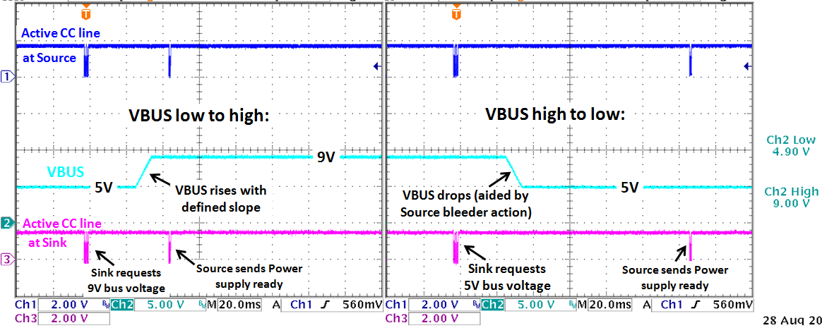
Figure 17
The CC line communication between Sink and Source will
look like below :
1. The Sink will first request Source
capabilities.
2. The Source will provide its source
capabilities.
3. The Sink will then request a
suitable power profile from the Source capability list.
4. The Source will accept the request
and start to make changes to the BUS voltage. The Sink will minimize the bus
loading during BUS voltage change. The Source will increase the VBUS voltage
with a defined slew rate.
5. After the BUS voltage has reached its final
value, the source will wait until the BUS has stabilized and then will send
a Power Supply Ready signal. The Sink will now increase the BUS loading
again.
When the Sink wants to reduce the Bus voltage a similar
communication sequence will happen.
But during the VBUS reduction, the Source will also
activate a bleeder (VBUS discharge) to help reducing the bus voltage faster.
The Source will wait a bit longer for VBUS stabilizing and will
then send Power Supply ready signal.
This communication method ensures that any power change
on the BUS is always within capability of both Source and Sink. As soon as
the Type-C cable is disconnected, the BUS voltage is removed, and any new
connection will start with cable connection check and the lowest bus voltage
(5V). This will avoid any damage when plugging cables from one device into
another device.
USB PD communication makes use of the Bi-phase Mark
Code (BMC). This code is a single wire communication, where a logic 1 is
transmitted by a hi-low change and a logic zero is transmitted as either a
fixed high level or a fixed low level. Each data packet consists of a
low-high-low sequence preamble, SOP (Start Of Packet), Header, message data
bytes, CRC error checking and EOP (End Of Packet). See Figure 18.
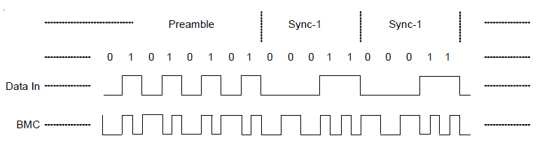
Figure 18
Just how dense the communication packets actually
are can be seen in Figure 19 which captured the PD communication after
requesting a VBUS voltage increase. The zoomed section shows the preamble
sequence.
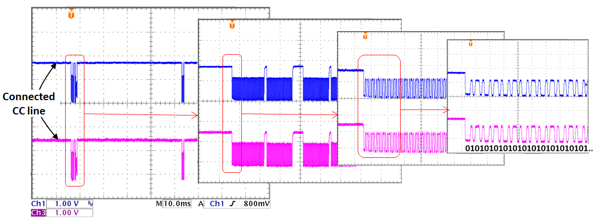
Figure 19
The BMC data can be decoded by USB PD decoders like
Ellisys EX350 Analyzer. These tools will capture PD data, show the meaning
of each packet, and show the timing related data with Vbus value, and CC
waveform. See Figure 20.
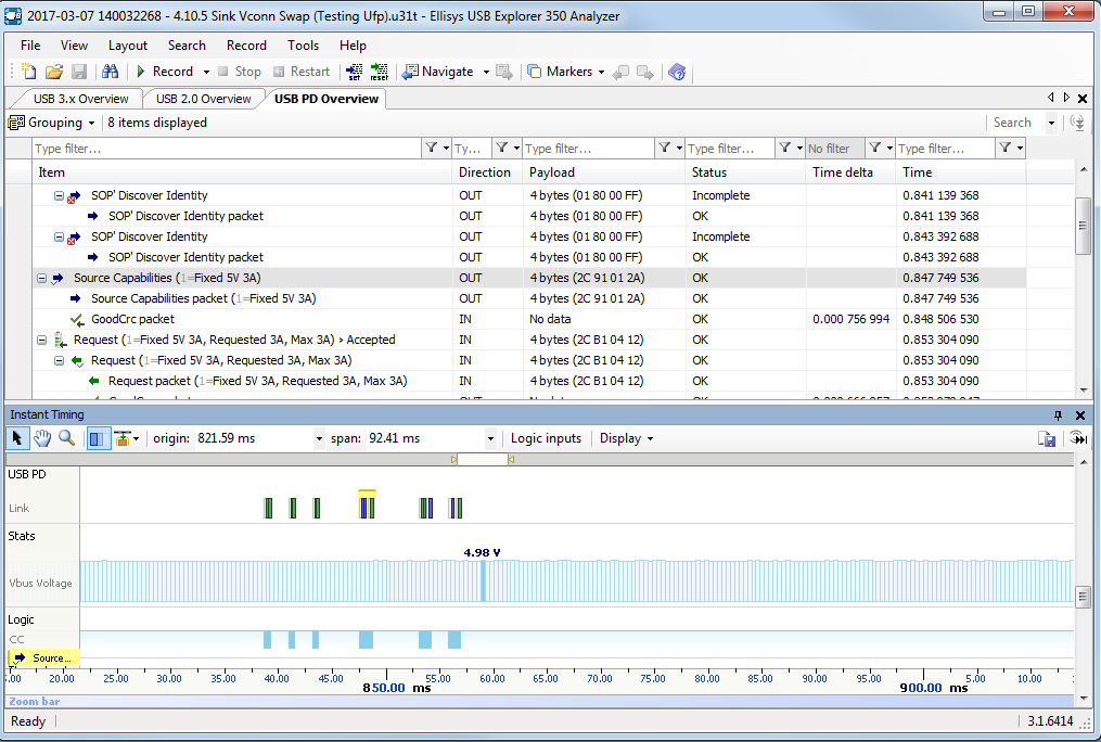
Figure 20
Power profiles
The USB PD 3.0 specification defines the following
power profiles :
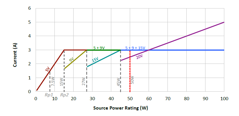
Figure 21
Four different discrete voltage levels are defined :
5V, 9V, 15V and 20V. For the 5V, 9V and 15V, the maximum current is 3A. The
20V profile can be max 20V/3A (60W) for normal cables but it can be
increased to 20V/5A (100W) when using special e-marked cables. A system that
supports a certain maximum voltage / power level must support all lower
voltage / power levels as well.
E-Marked cables
USB Type-C specifies various cables : For low speed
USB2.0 cables, there are no special requirements except that cable current
rating is 3A. Cables that support Superspeed USB3.1 data transfer or can
carry currents higher than 3A must be electronically marked. Figure 22 shows
the situation where the cable contains an IC that identifies the cable
characteristics (eMark IC). Active cables also can contain a re-driver IC
for signal conditioning. These ICs need to receive power from one of the
cable’s VCONN pins.
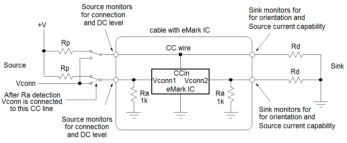
Figure 22
Cables with an eMark IC will have an internal 1k
pull-down resistor Ra on the VCONN pin, so Ra has a lower value than Rd
which is typically 5.1k. After inserting this type of cable, the Source will
see both CC1 and CC2 pin voltages dropping. The voltage levels will tell the
host which pin is pulled down by the Source via 5.1kΩ Rd resistor and which
pin is pulled down by the cable 1kΩ Ra resistor, so cable orientation can
still be determined. The Ra pull down action will also tell the Source that
a VCONN 5V power needs to be applied to that CC pin for powering the eMark
IC.
Figure 23 shows an example measurement where a power
provider (Source) is being connected to a power consumer (Sink) by means of
a cable with eMark IC. (In this case the cable was twisted)
|
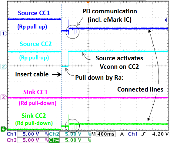
Figure 23
|
It can now be seen that when the cable
is connected, one of the CC lines at the Source is now pulled
down to a very low level due to the low Ra value (1kΩ) on the
VCONN pin.
The Source will sense this and will know
that the cable contains an E-mark IC. It will then apply a 5V
VCONN supply to this CC line to power the cable internal
electronics.
PD communication will take place, which
now includes the data communication between Source and eMark IC
(called SOP’ or SOP’’) and the data communication between Source
and Sink (called SOP communication)
|
Dual Role for Power (DRP)
Some USB Type-C devices can act as Source and Sink,
the so called Dual Role for Power (DRP) devices. These devices will toggle
the CC1 and CC2 pins high-low before connection is made. If two DRP devices
are connected together, both end of the cable show toggling CC lines as is
shown in Figure 24.
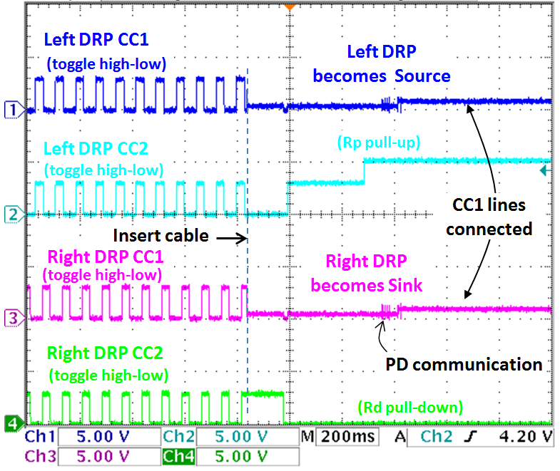
Figure 24
In this connection event, the left DRP took the role
as Source and the right DRP became Sink. But it could also be vise versa,
unless one DRP has set a preference as Source (i.e. when it’s powered by an
external adapter) or preference as Sink (i.e. when it is powered by a
battery).
Power Role swapping can be done while connected:
When two DRP’s are connected together, either side can request a power role
swap. Figure 25 shows an example of Power Role Swap.
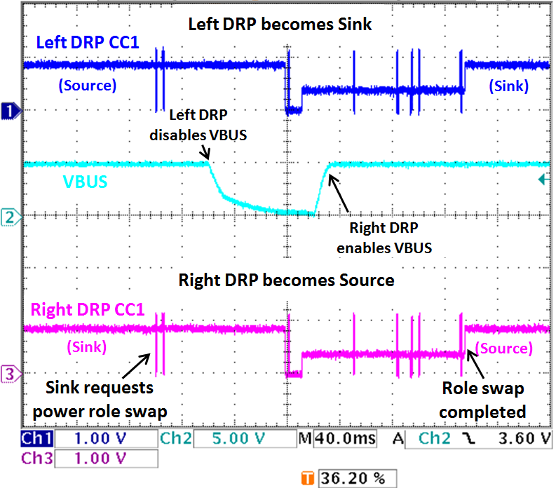
Figure 25
3. Introduction to Richtek USB Type-C PD solutions
Since the start of the USB Type-C PD specification
definition, Richtek has been a member of the USB Implementers Forum (USB-IF)
in order to stay updated with the latest developments of the standard.
Richtek has been developing innovative solutions for a wide range of USB
Type-C PD applications, from USB-PD power adapters, Car Chargers, Type-C cable e-Mark ICs to Type-C Dual Role Power PD port controllers which use the latest USB3.0 PD protocol to support Direct Charging systems. Figure 26 shows some
evaluation kits and development board for various USB Type-C Power Delivery
applications.
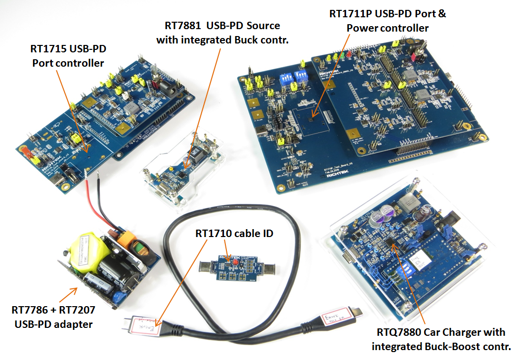
Figure 26
For USB Type-C Power Adapters with Power Delivery applications, we have developed RT7786 Flyback controller which works
together with RT7207 USB Type-C PD controller at secondary side. The wide
operation range of RT7786 and RT7207 make the output adjustable from 3 to
20V, and by using synchronous rectification via RT7207’s embedded
synchronous rectifier driver the rectifier losses at high output currents
are minimized.
RT1715 is a tiny (1.38 x 1.38mm CSP) but powerful
USB Type-C controller suitable for Sink or Source or Dual Role Power
Delivery applications. Supporting USB PD 3.0, VCONN power, Alternate Mode,
this IC can be used in a wide range of PD controller applications, like
Smart Phone, Hard drive or Tablet PC.
RT1711P is a full-featured USB Type-C controller
suitable for Sink or Source or Dual Role Power Delivery applications and
includes full dual role power path control, external DC converter output
voltage control, VBUS bleeder discharge and VBUS current sense. Supporting
USB PD 3.0, VCONN power, Alternate Mode this IC can be used in almost any
USB Type-C application with Power Delivery like Smart-Phone, Hard-drive,
Monitor, Notebook PC, Dongle or Car Charger.
RTQ7880 is an automotive grade USB Type-C PD Source
with integrated Buck-Boost controller. Its wide input voltage range in
combination with a Buck-Boost makes it suitable to be powered from Car
batteries and provide VBUS power from 5V/3A up to 20V/5A for charging any
USB-C device in a car environment. Supporting USB PD 3.0, VCONN power,
Alternate Mode and fully programmable cable drop compensation, this IC can
be used in wide range of USB Type-C Provider applications.
RT7881 is a USB Type-C PD Source with integrated
Buck controller for USB Type-C Provider applications. Having similar
features as RTQ7880, it can be used in wide range of USB Type-C Provider
applications that are powered from an input voltage that is higher than the
maximum required VBUS voltage.
RT1710 is a Cable ID (e-Mark) IC for passive and
active USB Type-C cables, like cables with 5A current capability or cables
with re-drivers for signal conditioning. RT1710 supports SOP’ communication,
and features embedded Ra / VCONN for both cable ends, isolation diode,
embedded MTP (multi-time rewritable memory for VDM data, with I2C
bus for writing VDM data and custom structured VDM writing through the CC
pin.
4. RT7786 & RT7207 Power Delivery Adapter
Conventional USB adapters for 5V only are relatively
straight-forward designs, as the output voltage is fixed and power levels
are relative low. But USB adapters with Power Delivery require that the
adapter output voltage can be varied over a wide range and they need to
provide higher power levels which can easily result in thermal issues in
small travel adapter form factors.
The Richtek RT7786 flyback controller is specially optimized for USB with Power Delivery : It can deliver a wide output voltage range, with adaptive loop gain control for maintaining stability, adaptive over-current and over-voltage protections, a wide VDD range allowing wider Vaux range, higher driver capability for driving large MOSFETs, has 30mW low power standby and SmartJitter for low EMI emission.
At secondary side RT7207 takes care of the flyback
converter output voltage control by controlling an opto-coupler based on
output voltage and current sensing. RT7207 also integrates an MCU to handle
the USB PD protocol, including BMC coding transceiver. The build-in charge
pump can ensure sufficient SR MOSFET gate drive even when output voltages
are below 4.5V. This allows output voltages down to 3.3V (3.0V for RT7207K)
allowing Programmable Power Supply (PPS) operation for Direct Charge
applications. The embedded driver for controlling a synchronous rectifier
can work in both DCM and CCM mode which increases the converter efficiency
at high loads. RT7207 has an OTP memory which allows programming of many
parameters, like over-current and over-temperature protections, and
programmable cable compensation. RT7207 can also be used in BC1.2 DCP
applications which make use of D+/D- pins for output voltage & current
setting. The basic schematic of an adapter using RT7786 and RT7207 is shown
in Figure 27.
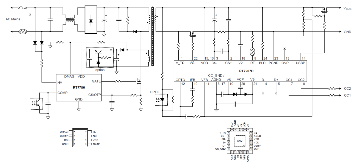
Figure 27
A note about CC1/CC2 pin voltage rating: In the USB
Type-C connector, the CC1/CC2 pins are adjacent to the VBUS pins. Due to the
small pin pitch of the connector, there is a risk that during cable connect
or disconnect a short could occur between VBUS and CC1/CC2, resulting in
maximum 20V on the CC1/CC2 pins. Richtek USB-PD controllers like RT7207D
therefore have 22V voltage rating for the CC pins which make them more
robust.
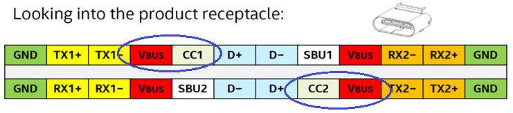
Figure 28
RT7786 + RT7207D reference design is available for
evaluation purposes. Figure 29 shows a 60W USB PD travel adapter design,
capable of delivering 5V, 9V, 15V and 20V at 3A from a full range mains
input.
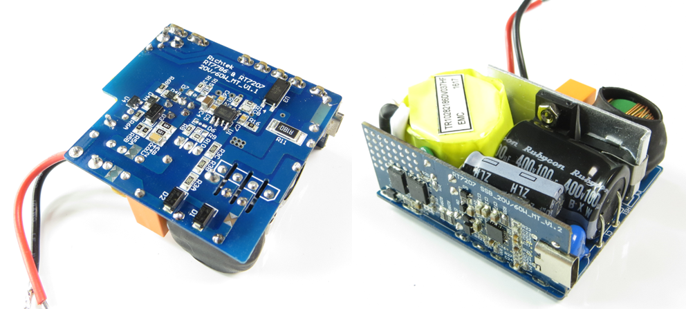
Figure 29
The design dimensions are 53 x 50 x 23mm, has an
efficiency of over 93% at 60W output, achieves less than 50mW no-load
standby power and has been tested to pass USB IF compliance test, as well as
DOE-6 and CoC Tier-2 PSU efficiency requirements with good thermal results.
5. USB Type-C and Power Delivery in car charger
applications
USB Type-C only solutions
Currently USB Type-C connectors are gradually being
introduced in cars as well. Most car makers start with Type-C only,
providing 5V VBUS up to 3A. For these applications, a standard USB Type-C
only controller with a Buck converter can be used. Figure 30 shows an
example of a Type-C only solution for car charger application.
|
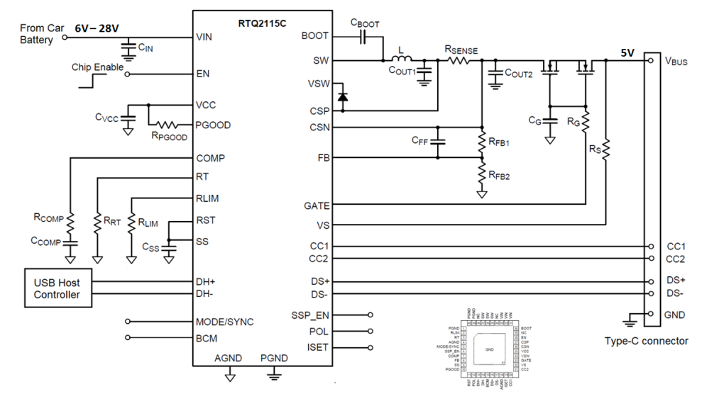
Figure 30
|
RTQ2115C is an automotive grade Type-C
DFP controller + 3.5A buck converter with 3V to 36V input
voltage range. It includes CC line sensing and current
advertising, VBUS current sense and On/Off control, VCONN supply
control and cable polarity detection & output. It also includes
D+/D- sensing BC1.2 SDP/CDP/DCP modes and divider mode / 1.2V
mode detection.
|
USB Type-C car charger with Power Delivery
To implement USB Type-C with Power Delivery in car
systems, it depends on the battery input range and VBUS output range whether
a buck converter can still be used. In Power Delivery systems that only
require power profiles of 5V/3A and 9V/3A, a buck converter may still be
acceptable. In such systems, RT7881 may be used. RT7881 is a
USB Type-C PD Source with integrated Buck controller for USB Type-C Provider
applications. See Figure 31.
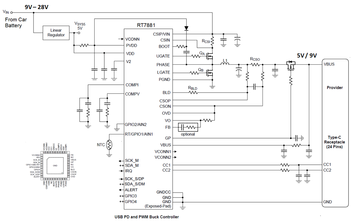
Figure 31
|
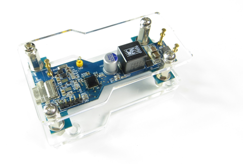
Figure 32
|
RT7881 integrates a Cortex M0 MCU which
controls all USB-PD communication, smart control of the
Buck-controller section including some firmware based
protections and customized functions.
Critical protections like VBUS OVP/USB
and OCP are all hard-ware based for fastest response. Output
voltage can be fine-tuned in 12mV/step, allowing digital cable
voltage drop compensation and Programmable Power Supply (PPS)
function.
Figure 32 shows the RT7881 EVB in a
typical Car Charger form-factor.
|
USB Type-C car charger with Power Delivery full output voltage range
For car battery powered charger systems that need to
be able to supply the complete USB-PD output voltage range from 5V to 20V,
the power converter needs to be a buck-boost type. For these applications
Richtek has developed RTQ7880, an automotive grade USB Type-C PD Source with
integrated Buck-Boost controller for USB Type-C Provider applications. See
Figure 33.
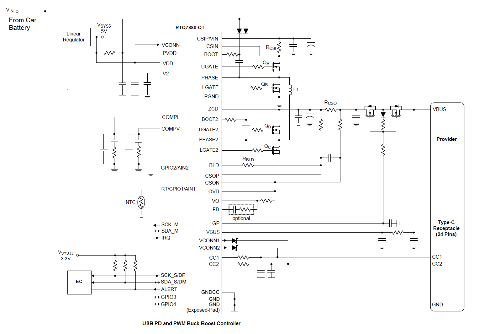
Figure 33
The buck-boost converter consists of a full bridge.
In Buck mode, QA and QB are switching, and QD
is on, QC is off. In boost mode, QA is on, QB
is off and QC and QD are switching. The transition
from buck to boost mode is seamless.
Similar to RT7881, RTQ7880 includes a Cortex M0 MCU
which controls all USB-PD communication and smart control of the Buck-Boost
controller section.
The buck-boost controller is fully configurable,
with programmable switching frequency, current sense, force-PWM or PSM mode,
output voltage can be fine-tuned in 12mV/step, allowing digital cable voltage drop
compensation and Programmable Power Supply (PPS) function. RTQ7880 includes
a charge-pump for blocking MOSFET gate drive, allowing the use of cheaper
N-type blocking MOSFETs. CC1/CC2 lines are 20V tolerant, allowing CC line to
VBUS short-circuit. VCONN supply with current limit is included, for driving
systems with e-marked cables for output powers up to 100W (20V/5A).
|
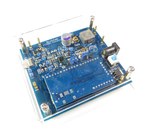
Figure 34
|
RTQ7880 can be used as stand-alone
charger provider, but it can also be used in combination with an
Embedded Controller for added data communication with MUX.
Figure 34 shows the RTQ7880 evaluation
board which is capable of providing up to 60W (20V/3A) of output
power. The evaluation board includes a Richtek bridge board for
connection to a PC, to read the VBUS voltage and current status
and control PD functions.
The firmware of RTQ7880 is located in a
multiple programmable MTP memory. It can be re-flashed via the
Richtek bridge-board, but the IC can also be configured to be
programmable via the USB Type-C bus for firmware updating in the
field.
|
Besides car charger, RTQ7880 can also be used in
provider only applications like USB-PD display or hub. The buck-boost
converter makes it possible to power these systems from normal 12V input
power supply.
6. USB Type-C PD Dual Role Power (DRP) controllers
Previous USB applications used USB On-The-Go (OTG)
to be able to use the USB port for both charging and delivering power. In
USB type-C applications, Dual Role Power (DRP) controllers make it possible
to configure the type-C port as Source or Sink. DRP controllers need to be
able to switch the power path from source to sink and for Power Delivery
need to be able to configure the voltage regulator for the correct output
voltage. Richtek has developed a number of USB type C PD controllers with
DRP :
|
Part Number
|
PD version
|
Power Delivery
|
Dead Battery Support
|
20V CC line Protection
|
Power Path Control
|
VCONN Support
|
Package
|
|
RT1711H
|
USB-PD2.0
|
100W
|
Yes
|
Yes
|
No
|
Yes
|
CSP-9B 1.38x1.34
|
|
RT1716
|
USB-PD3.0
|
100W
|
Yes
|
Yes
|
No
|
No
|
CSP-8B 1.38x1.34
|
|
RT1715
|
USB-PD3.0
|
100W
|
Yes
|
Yes
|
No
|
Yes
|
CSP-9B 1.38x1.34
|
|
RT1711P
|
USB-PD3.0
|
100W
|
Yes
|
Yes
|
Yes
|
Yes
|
QFN-24L 3.5x3.5
|
All devices include the full type-C transceiver
including Rp and Rd resistors. In all cases, the Type-C controller will work
in combination with an Embedded system Controller (EC), which communicates
with the Type-C controller via I2C bus. Figure 35 shows two
possible ways to design a typical DRP solution like a Mobile Phone :
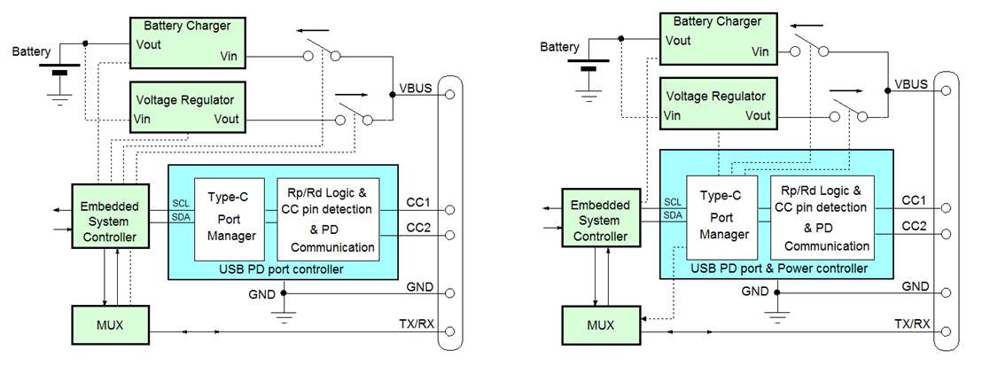
Figure 35
Figure 35 left side shows a DRP solution which makes
use of a USB Type-C PD port controller. The controller takes care of all
Type C port detection and communication and stores the information in
internal registers.
The embedded system controller will read the
registers and makes the decisions, activating MOSFET switches and
controlling voltage regulator for Source role or battery charger for Sink
role. In this case the USB PD port controller can be RT1711H, RT1715 or
RT1716.
Figure 35 right side shows a DRP solution which
makes use of a USB PD Port and Power controller. This controller includes
functions like external MOSFET control, voltage regulator control and data
MUX control. The embedded system controller still reads the registers and
makes the decisions regarding power role, but the commands are all send to
the PD power controller which activates the power path and control
functions. VBUS Protection functions like Bus over voltage and over current
can be executed immediately without EC intervention. In this case the USB PD
port controller can be RT1711P.
Since many DRP applications work with a battery, the
system has to be able to start-up when the battery is dead or has been
deeply discharged. Above mentioned controllers all support dead-battery
function, which means that even when no power is applied, the Type-C
controller will activate Rp resistors when the cable is connected, so a
Source will sense the pull-down action on the CC wire and activate the VBUS.
The Sink will then be able to wake-up the EC and the system can operate
without battery or try to recharge the battery.
Figure 36 shows a typical application of a USB Type-C
DRP solution in a Smart-Phone using the Type-C PD controller RT1715, which
takes care of the CC line detection and communication and support for VCONN
to power e-marked cables.
|
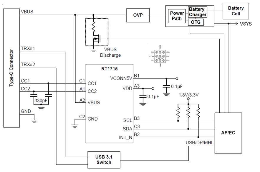
Figure 36
|
The VBUS power control in this case is
handled by the embedded controller (EC) and a battery charger
like RT9466.
The EC reads the RT1715 registers, decides
the power role and sets the battery in charge mode (Sink role)
or OTG mode for Source role. The battery charger Power Path
control is used to switch on / off VBUS.
|
For development purpose, Richtek provides evaluation
boards for RT1711H, RT1715 and RT1716.
Figure 37 shows the evaluation board for RT1715, which
includes an embedded controller, voltage regulators, and switches for many
different hardware configurations. A GUI tool is provided which communicates
with the EC to read (via RT1715 registers) the USB Type-C port status, set
the power role and select various power profiles.
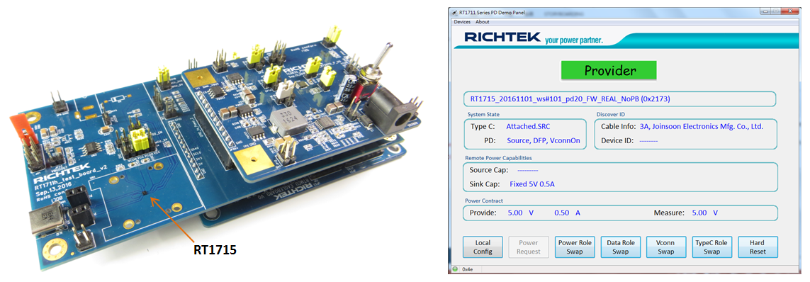
Figure 37
RT1711P is a full-feature USB Type-C controller
suitable for Sink or Source or Dual Role Power Delivery applications. Figure
38 shows RT1711P in a DRP application with full dual role power path
control, external DC converter output voltage control, VBUS over current and
overvoltage sensing and bleeder discharge. Supporting USB PD 3.0, VCONN
power and Alternate Mode, RT1711P can be used in almost any USB Type-C
application with power delivery like Smart-Phone, Hard-drive, Monitor,
Notebook PC, Dongle or Car Charger.
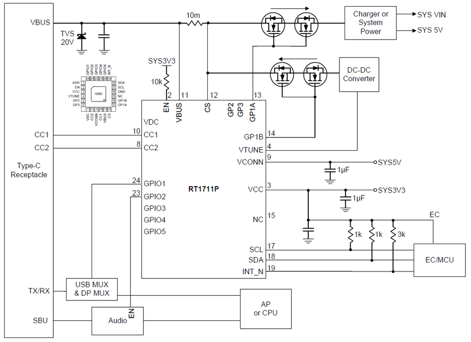
Figure 38
Also for RT1711P evaluation boards are available to
test the device in various configurations.
Figure 39 shows the evaluation board for RT1711P, which
includes an embedded controller, voltage regulators and switches for all
hardware configurations, with Power Delivery range from 5V/3A to 20V/3A. A
GUI tool is provided which communicates with the EC to read (via RT1711P
registers) the USB Type-C port status, set the power role and select various
power profiles.
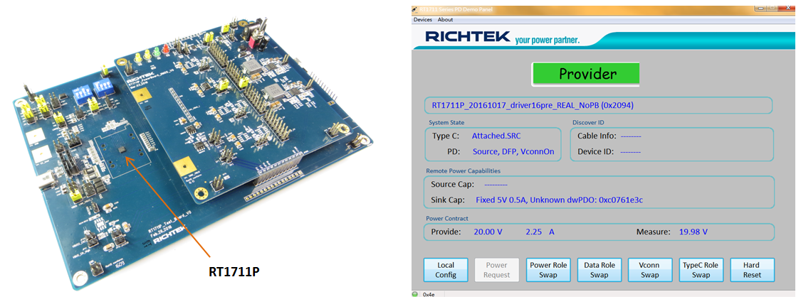
Figure 39
7. Cable ID for USB type-C passive and active cables
USB Type-C Cables that support Superspeed USB3.1
data transfer or carry currents higher than 3A must be electronically
marked, which means the cable connector will include a small IC that
contains information about the cable properties, data performance, vendor
identification, etc. This e-mark IC will be powered by the VCONN line of the
Source, and transmits its data over the CC line. The e-mark IC will include
a Ra 1kΩ pull down resistor on the VCONN pin to let the Source know the
cable contains an e-mark IC. Once the cable is connected, BMC communication
will take place between Source and e-mark IC.
RT1710 is specially designed for providing a
flexible solution for electronically marked cables. It has two input supply
pins VCON1 and VCON2 with blocking diodes and embedded Rd resistors to allow
it to be powered from both cable ends as shown in Figure 40. The RT1710
communication supports USB Power Delivery Structured VDM Discover Identity
commands directed to SOP', and is fully certified to meet USB-IF
requirements. Its slew rate controlled BMC communication minimizes the EMI
effects.
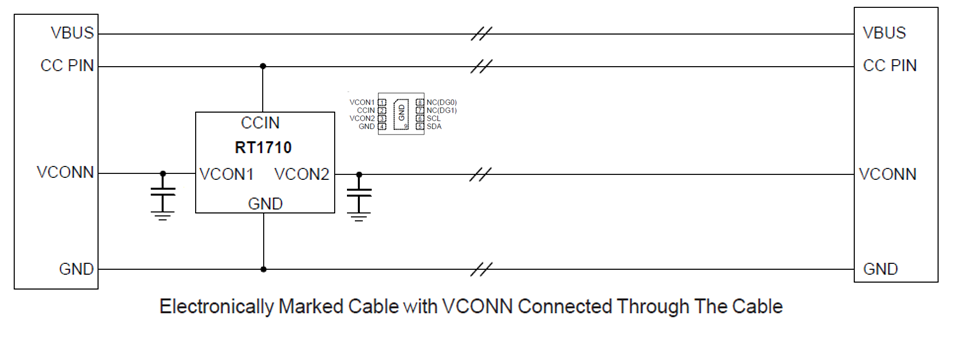
Figure 40
Although most cables will adopt the single IC
solution of Figure 40, some cable manufacturers may wish to place two ICs,
one in each connector, thereby reducing one wire in the cable. (See Figure
41). Each IC is now powered from the VCONN pin at each cable end. Since only
the Source will provide VCONN voltage, only one IC is active at the time.
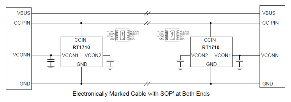
Figure 41
RT1710 has an embedded Multi-Time Programmable
memory for storing the VDM data. This data can be written into the MTP
memory by using the Richtek programming tool. Figure 42 shows the RT1710
evaluation board and the programming tool.
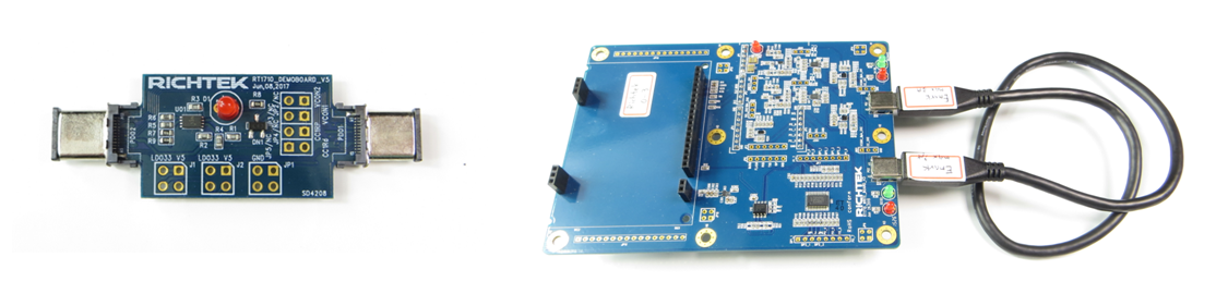
Figure 42
For cable production and testing, the Richtek RT1710
production test kit and program can be used.
The test kit consists of a programming tool with LCD
display which is controlled a PC using the USB port.
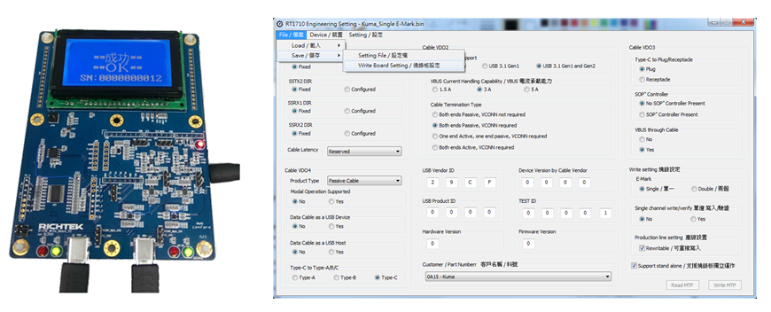
Figure 43
The programming tool has two USB Type-C ports, and
can program and test cables with single or dual e-mark IC. The test kit will
be unique for each customer, with dedicated vendor ID. VDM data includes
cable serial number, which will be automatically updated each programming
cycle. The LCD screen will show the serial number and pass or fail message
for quality checking.
8. Summary
With the introduction of the USB Type-C standard,
a lot of new functionality is introduced. It is important to understand the
basics of the USB type-C Power Delivery standard and capability in
order to determine the application requirements.
Richtek is continuously expanding its power
management solutions for various USB Type-C with Power Delivery applications, from Type-C power adapter, Car charger, Display, Power Bank,
Cable ID to full function Dual Role Power applications like Smart Phones.