LED Backlight System and Power Solutions
Abstract
Since the 2010’s, cold cathode fluorescent lamps (CCFL) in liquid crystal display (LCD) backlighting have been gradually replaced by light-emitting diodes (LED). This is because LEDs, which contain no mercury, have outperformed in thermal dissipation efficiency, color rendition and cost reduction.
Contents
Various LCD TV manufacturers, one after another, have eagerly adopted LED backlighting technology for LCD to achieve the feature of low profile, aiming to increase market share on the arrival of the new home TV generation. The market penetration of LED backlit models has been soaring that most of the LCD TVs are LED backlit on Taiwan’s market today.
LED backlighting technology can be divided into two groups: direct-lit type, and edge-lit type. LEDs, used in direct-lit type backlighting, can be either white or RGB. The differences between these two types and LED power solutions in system perspective will be investigated in this application note. For example, the functional block diagram of a 4-CH LED driver, RT8510, used in notebook computers, is illustrated in Figure 2. The upper block is Boost Converter, providing the voltages needed for LED strings, and the lower block is Constant Current Dimming Controller.
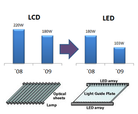
Figure 1. LED LCD TVs consume less power than CCFL LCD TVs
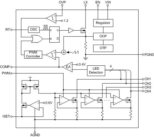
Figure 2. The functional block diagram of a LED driver RT8510
1. Edge-Lit Type vs. Direct-Lit Type Backlighting
Backlight Modules, as the lighting source of LCDs, consist of light sources, light guides and backlight diffuser plates, etc. As LCD TVs and laptops have become increasingly prevalent, the development focus is to incorporate energy-efficient LED backlight modules into the systems in response to the trend of large-scale and low-profile panels.
For edge-lit LED backlighting technology, white LEDs are placed around the four sides of the LCD, and the light is emitted through between the LCD panel and the reflector sheet, by which the light is reflected to the back of the LCD panel. The light guide plate spreads the light evenly across the back of the LCD. This is by far the most commonly used LED backlighting technology with advantages of low cost and low profile.
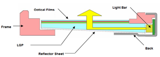
Figure 3. Edge-lit Backlight Module
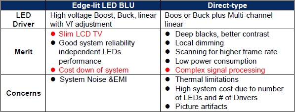
For direct-lit backlighting technology, LEDs are placed in a flat array behind the light guide plate and the LCD screen, which the light is directly emitted to. This method allows for fast locally dimming LEDs for specific areas of brightness on the screen to greatly enhance dynamic contrast. The disadvantage, however, is that more LEDs are to be used, which will then increase product cost and also the thickness of the backlight module. White LEDs are most commonly used for LED backlighting, while for some high-end models, RGB LEDs are used for wider-gamut color rendition.
Table 1. Comparison of Edge-Lit Type and Direct-Lit Type Backlighting Technologies
2. Important Characteristics for LED Driver ICs
Generally, users will consider the following characteristics when choosing LED driver ICs:
1.LED Current Accuracy: LED current is set by the value of the external resister RISET connected from the ISET pin to ground. This current is mirrored by a current mirror to the current source. The error percentage of the current values from the theoretical calculation and the actual current is called as LED Current Accuracy.
2.LED Current Matching: There are many ways to configure LEDs in an array. If LED strings are connected in parallel, the LED current through each LED string must match with each other. This will increase the brightness uniformity among various LED strings. LED current usually is directly proportional to LED brightness.
3.Dimming Type: Dimming has become an essential feature of LED drivers. And it can be categorized into Analog Dimming and PWM Dimming. PWM Dimming can achieve better color rendition due to no shift in the chromaticity coordinates. However, it is more susceptible to audible noise problems. The approach to tackle this will be proposed in the later session.
4.LED Current Linearity: For PWM dimming, the output LED current varies with PWM duty cycle. The relationship between these two is described as linearity. The LED current linearity will become degraded for low PWM duty ratio and high PWM dimming frequency. Figure 4 displays the RT8510 PWM Dimming Linearity.
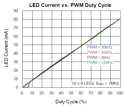
Figure 4. RT8510 PWM Dimming Lineartiy
3. Power Solutions
The commonly used power architecture for today’s TV models is that LLC or Flyback systems provide DC power supply to boost or buck converters, which then drive LED arrays, and LED Current Regulator clamps the current at the desired LED brightness. Nevertheless, in recent years, LED arrays can be found directly driven by an LLC or a Flyback system, while the voltage of the previous stage is adjustable by controller ICs.
Figure 5 is the application schematic diagram of a power solution. The RT8525, on the left-hand side, as a DC-DC Boost Converter, provides sufficient voltages to drive LED arrays. The RT8300, as a Current Regulator, provides constant current and dimming function. DHC (Dynamic Headroom Control) connects these two ICs as a feedback control. When the backlight module is turned on, the forward voltage, Vf, of the LED will decrease due to the increasing temperature. If the output voltage remains fixed, the terminal voltages on LED 1~4 pins will then increase. It will cause both the power dissipation and the temperature of the RT8300 to rise. Consequently, it will result in the decrease of overall efficiency and the failure of surface temperature requirement for the ICs. Therefore, there must be a mechanism to make the boost converter lower down its output voltage.
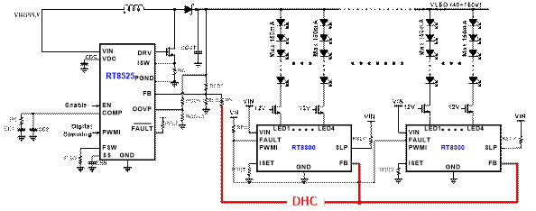
Figure 5. The application schematic diagram of a power solution
Dynamic Headroom Control (DHC) function is created for this purpose. The RT8300 will find out which channel has the lowest terminal voltage on LED 1~4 pins among all LED channels and will clamp the desired operating voltage by the curve in Figure 6. This voltage has a linear relationship with the LED current.
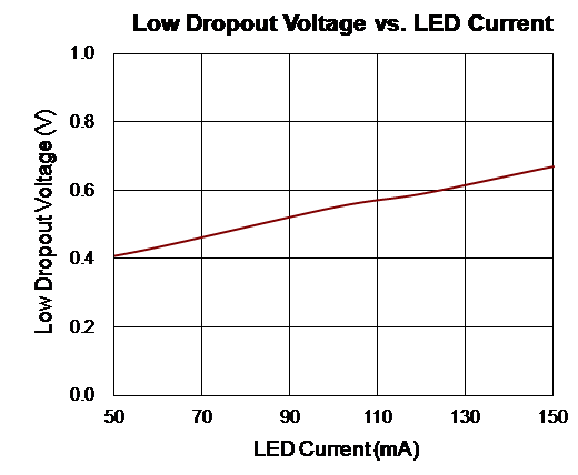
Figure 6. The linearity characteristic of RT8300
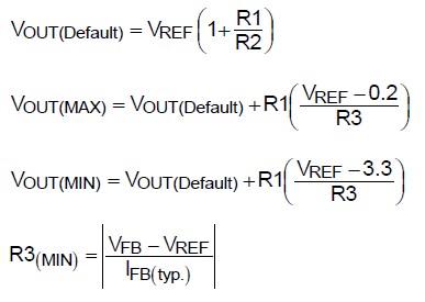
If the pin voltage for that lowest-voltage channel is higher than the corresponding value in Figure 6, the RT8300 VFB pin will be set high. Through R3 to VREF, the output voltage (VLED) will be lowered. Vice versa, if the pin voltage is too low, VFB pin will be set low and the output voltage will be pulled higher. Figure 7 shows the schematic and the corresponding equations, which are based on the Superposition Theorem.
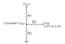
Figure 7. The RT8300 DHC schematic diagram
For different applications, the wattages of their backlight modules will be different. Generally, the larger LCD panels, the more LED arrays to provide for the desired brightness will be needed. The power dissipations for ICs and power devices will thus be increased, which deteriorates the thermal performance. Compared to the power solutions for the backlights of notebook computers, the desktop monitors demand greater power. Therefore, it is better the MOSFETs are connected externally instead. For applications of even higher wattages, such as LCD TVs, even the drivers of current source devices will be connected externally in order to lower down the surface temperature of ICs. The following lists Richtek LED backlight power solutions for various applications.
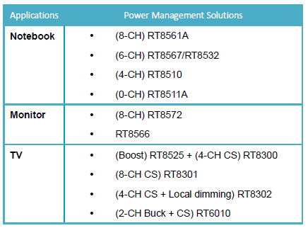
Figure 8. The power solutions for the various applications
4. The Solutions to Audible Noise Problems
All electronics products have specifications with regard to audible noises. When portable electronics products become more and more prevalent, the noise specifications for their backlight modules are even stricter. The audible noises usually arise when the applications operate in PWM dimming mode. The noises mainly results from the resonance, caused by the output capacitance, MLCC, and the output current switch. In PWM dimming, PWM LED current switches between heavy and zero loads. The abrupt changes of the loads will increase the ripples of the output voltage. Such ripples to human ears are audible noises. Figure 9 shows the waveform diagram of the RT8510 when dimming.
CH1 = PWM, CH2 = Vout,ac, CH3 = VLX, CH4 = ILED
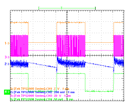
Figure 9. The waveform diagram of the RT8510 when dimming
There are many ways to solve the problem of audible noises. Below are a few examples for users as references:
1.Increase output capacitance values to reduce the output ripples: this method is simple and straightforward, but the drawback is the increase of cost.
2.Change the PWM dimming frequency to avoid the audible frequency range, which is about 20 kHz. However, the drawback is dimming linearity will be compromised.
3.Mixed Mode: At lower PWM duty ratios, just switch to Analog Dimming to reduce audible noises.
4.Phase Shift Function: In a multi-CH driver ICs, sequentially turn on each channel to improve the load transient performance.
5.Use larger OVP resistors: When PWM is off, larger OVP resistors will lower the load and the output dropout voltage, and so the noises can be reduced.
6.Replace with an MLCC from the noise reduction solution: The output capacitance will affect how large the ripples are. Large ripples may cause resonance in between the layers, which will induce noises. The noise-reduction capacitors have the superior performance over the cross-voltages, that is, less capacitance change at higher DC biases. Figure 10 shows the comparison of the equivalent MLCC capacitances between the new (noise-reduction) and conventional fabrication processes.
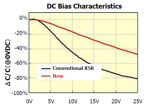
Figure 10. The comparison of MLCC equivalent capacitances between new and conventional fabrication processes.
5. Protection Mechanism
Generally, LED drivers have the following built-in protection mechanisms:
1.SLP (Short LED Protection): If any LED(s) in the LED string is connected short when mounted on the surface, the overall forward voltage Vf of the LED string will be lower, which will results in higher VLEDX terminal voltage. SLP is to detect whether the VLEDX voltage is too high. For some models, only the short channel will be off, while for others, it is the driver circuit to be turned off. Users can adjust SLP voltage via RSLP.
2.OLP (Open LED Protection): If any LED(s) in LED strings are in poor contact, whether in assembly or in use, OLP is to detect whether the VLEDX voltage is too low when power-on, and will send out the warning signal accordingly.
3.OVP (Over Voltage Protection): When the overvoltage occurs at the output voltage, OVP will detect it by the voltage divider. It will clamp the output voltage at the voltage set by OVP, without turning off the circuitry. Figure 12 shows the RT8300 protection mechanism flow.
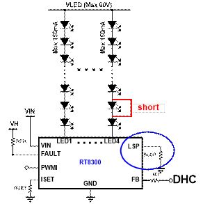
Figure 11. The RT8300 SLP diagram
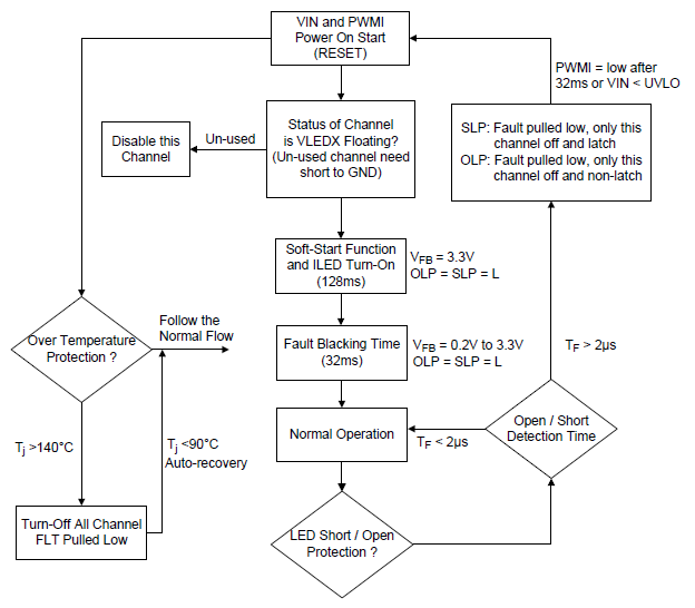
Figure 12. The RT8300 protection mechanism flow
6. 3D/Local Dimming
In recent years, the features of 3D and local dimming have been incorporated in high-end TV models. They are to be introduced as below:
1. 3D Dimming:
In 3D mode, due to the decreased PWM duty, the higher brightness from backlight modules is needed. The images perceived by human’s right/left eyes will be alternately displayed to generate the effect of field of depth. Figure 13 illustrates a 3D dimming functional diagram. The LED driver, RT-CVT, demands that the 3D-glasses shutters be synchronized with Main Board in order to effectively block left and right eyes alternately.
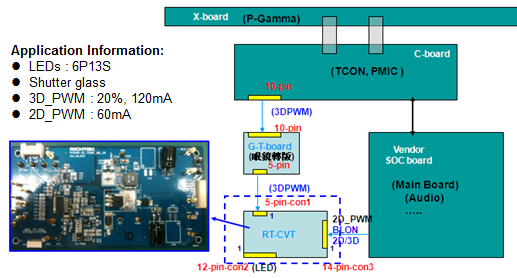
Figure 13. 3D dimming functional diagram
2. Local Dimming:
This approach is used for advanced models to enhance the contrast. The blacks with local dimming are perceived darker because the backlights of that section are dimmed. On the contrary, the backlights behind brighter sections can be brighter. Henceforth, local dimming has the advantage of consuming less power. Figure 14 illustrates an example of a 64-zone local dimming. The more zones the screen is divided into, the more noticeable the benefit of local dimming is. However, the trade-off is the complexity of control and cost will be correspondingly increased.
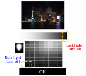
Figure 14. An illustration for a 64-zone local dimming
For local dimming applications, the limited bandwidth of the commonly used I2C Interface is no longer acceptable. For example, the RT8302, a 4-CH Programmable Current Sink Led Driver, uses the SPI Bus (Serial Peripheral Interface Bus) as the signal transmission interface instead. Figure 15 shows the RT8302 SPI interface application schematic diagram.
|
SPI Mode – Digital Interface Pins
|
|
CS(N)
|
Chip Select Input
|
|
SDO
|
Serial Data Output
|
|
SDI
|
Serial Data Input
|
|
VSYNC
|
Video Sync Signal Input
|
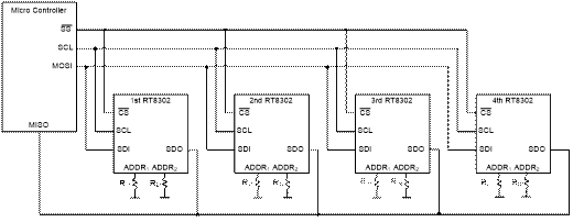
Figure 15. RT8302 SPI interface application schematic diagram
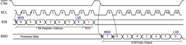
Figure 16 is the RT8302 Read/ Write instruction diagram as below.
Read Command:
Write Command:
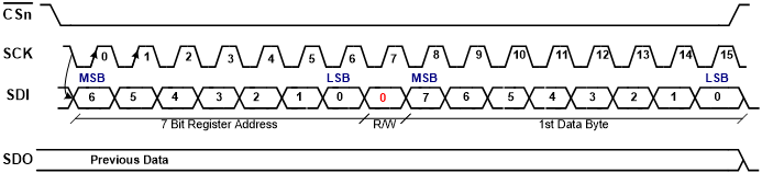
Figure 16. RT8302 SPI read/ write instruction diagram
7. Conclusion
The architectures for LED backlight driving systems vary in accordance with various requirements, such as energy efficiency, cost down and performance enhancement. The driver ICs should then be changed accordingly. Furthermore, to power LED strings, the power solutions should change with the applications (TV/ Monitor/ Notebook/ Tablet). Finally, to tackle the audible noises, to enhance the system efficiency, and to meet the surface temperature requirements for all the components are also important aspects to consider for customers.