Designing Applications with Lithium-Ion Batteries
1. Introduction
Lithium-Ion batteries have several advantages when compared with other battery types: They are light weight, and energy density of lithium-ion is typically twice that of the standard nickel-cadmium. Li-Ion batteries have no memory effect, and the self-discharge is 6 ~ 8 times less compared to nickel-cadmium. The high cell voltage of 3.6 volts is often sufficient to power applications from a single cell. These properties make Li-Ion batteries very popular in modern portable electronic applications.
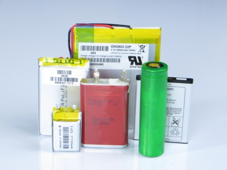
Figure 1
Figure 1 shows several types of Li-Ion and Li-Polymer cells, used in different applications, with capacities ranging from 200mAh to 2800Ah. Standard Lithium-Ion batteries normally use a rigid case, while Lithium-Polymer batteries often use a flexible foil type or pouch cell case, which reduces size and weight. Application wise, there are no significant differences in electrical characteristics between Li-Ion and Li-Polymer batteries.
When designing applications with Li-Ion cells, it is important to understand the battery behavior during charging and discharging, to ensure a safe application and best battery life time.
2. Single Li-Ion Cell as Power Source
When powering your application from a single Li-Ion cell, the application input range must consider the voltage fluctuation of the battery, which for most Li-Ion batteries ranges from 4.2V fully charged down to 3.0V fully discharged. Most applications will require some form of voltage regulation.
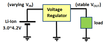
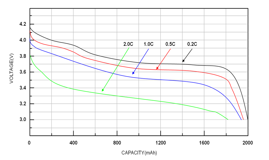
Figure 2
Figure 2 shows the typical discharge curves of a 2000mAh Li-Ion battery, from fully charged (4.2V) to fully discharged (3.0V) condition. The discharge rates are expressed as a ratio of battery capacity (C). At high discharge currents, the battery capacity cannot be fully utilized and the battery voltage will drop due to battery internal resistance.
Richtek offers a wide range of LDOs, buck, boost and buck-boost converters that can operate from the typical Li-Ion battery cell voltage range. Below are some examples applications.
Low IQ LDOs like RT9063 can be used to regulate the output voltage for micro power applications with minimal battery loading. The 1µA ground current ensures minimal battery drain in low power standby mode.
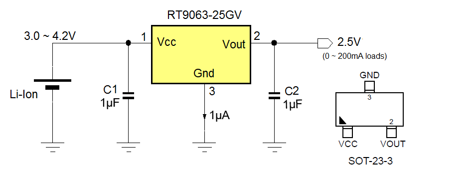
Figure 3. RT9063-25 application for low power applications with ultra low standby mode.
Low voltage buck converters like RT8059 will operate in 100% duty-cycle mode when battery voltage approaches the output voltage, increasing the useful battery range.
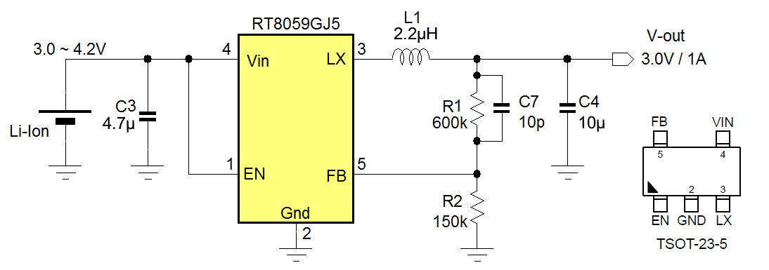
Figure 4. RT8059 3.0V application maintains regulation down to 3.0V battery voltage.
Boost converters like RT9276 can be used to produce a stable USB 5V supply at varying battery voltage and provide battery voltage monitoring function.
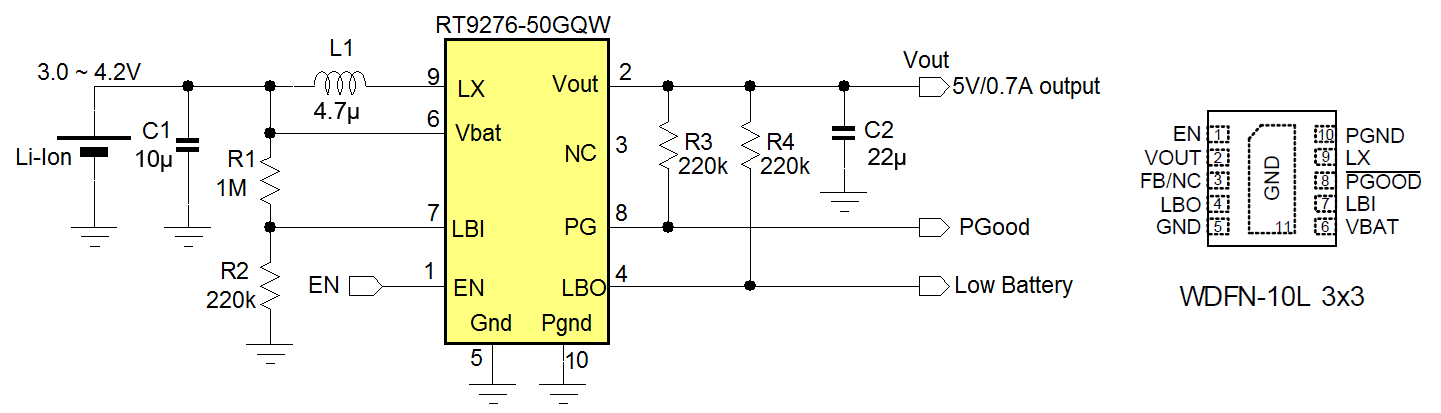
Figure 5. RT9276-50 application provides stable 5V from battery input.
Buck-boost regulators like RT6150A or RT6154A can be used when the output voltage lies in between the battery max and min voltage range, and with their four internal switches, they seamlessly switch over from buck to boost mode.
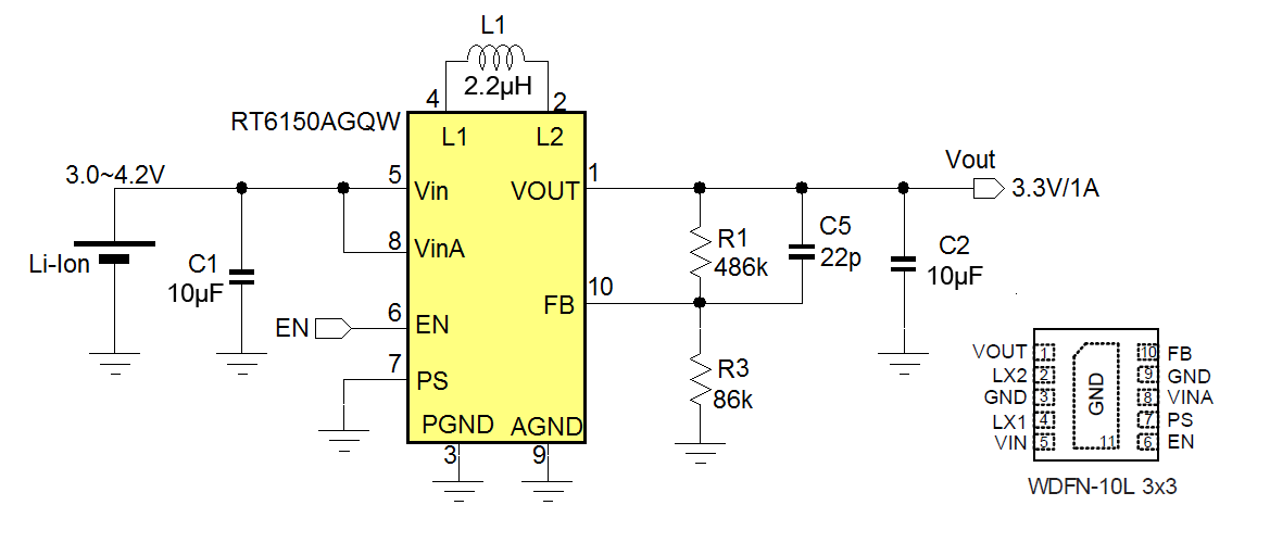
Figure 6. RT6150A automatically switches from buck to boost mode when battery drops below VOOUT.
Constant current boost converters are normally used for powering LEDs from Li-Ion batteries. For very low power levels (0.2W) charge pumps like RT9361A are used. For higher powers, boost converters like RT9285B (0.8W) or RT9293B (2.5W) can be used. For backlighting larger displays, multi-string boost LED drivers like RT8532 (6W) are used.
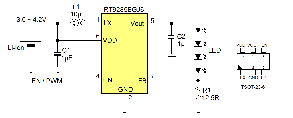
Figure 7. PWM dimmable RT9285B application for powering 4 WLEDs from Li-Ion battery.
General application remarks:
Most switching regulators have enhanced light load efficiency, thereby increasing the battery span in light load conditions.
Li-Ion batteries are sensitive to over-discharge, which is why many cells have built-in under-voltage protection circuits that switch off the cell when the cell is discharged below 2.5V. It is recommended to re-charge the battery or disconnect the battery from the system well before this battery internal protection is activated.
During battery installation, hot-plug events of Li-Ion batteries to an application that only contains ceramic input capacitors can lead to input voltage ringing, due to the resonance of the battery connection wire and low ESR ceramic input capacitor. The circuit designer should carefully check this behavior and insure the hot plug event will not cause voltage overstress to IC input circuits.
3. Battery Charging
Charging Li-Ion cells needs special care, as incorrect charging can lead to battery damage and unsafe conditions. Most Li-Ion chargers have pre-conditioning - constant current - constant voltage - current cut-off functionality as shown in figure 8 below.
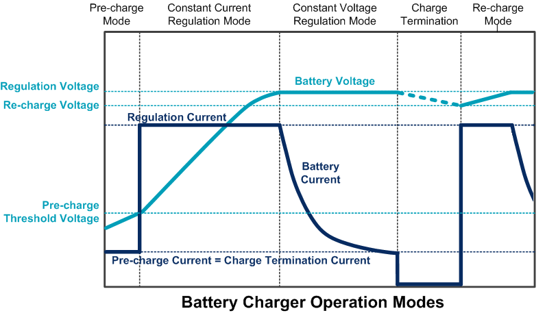
Figure 8
In case of deep discharge, the battery charger will first provide a low pre-charge current, to pre-condition the battery for normal charging. This low preconditioning current can also reset the battery internal under-voltage protection.
During the constant current regulation mode, the battery is charged with a defined current, usually between 0.5C and 0.7C (where C is the battery capacity in Ah).
When the battery voltage approaches the regulation voltage, (4.2V or 4.35V depending on battery type) the charge current drops gradually and the charger will work in constant voltage mode. This maximum regulation voltage needs to be accurately controlled to avoid over-charging which would damage the battery and result in unsafe conditions.
The battery is considered fully charged when the battery voltage is at its regulation voltage and charging current drops below a certain % of rated charge current (usually 5 ~ 10%) and then charging is terminated. It is not recommended to continuously trickle charge Li-Ion cells, as this will reduce battery life. Most chargers will start a re-charge cycle when the battery voltage drops below a certain level (usually 0.1 ~ 0.2V below the regulation voltage).
When Li-Ion batteries are not used for a prolonged time period, it is better to discharge them to around 40% (~3.7V) to reduce their aging effect.
Battery temperature during charging needs to be monitored and too high or too low battery temperature should stop the charging process. For most Li-Ion batteries, normal charging conditions can be applied within the 10°C ~ 45°C temperature range. Charging should be cut-off when battery temperature is below 0°C or above 60°C.
Richtek has a wide range of Li-Ion chargers from linear to switching types. Linear charger topology is often used with batteries up to 1000mAh, while switching chargers are used for larger capacity batteries which can be charged with higher currents (>1A), or when using adapters with higher input voltage.
RT9525 is a linear charger with Auto Power Path, which allows the application to be run from adapter power, but it will gradually move back to battery power when the adapter input current limit is exceeded. RT9525 also contains many protection features like input overvoltage protection, output short protection and load disconnect function.
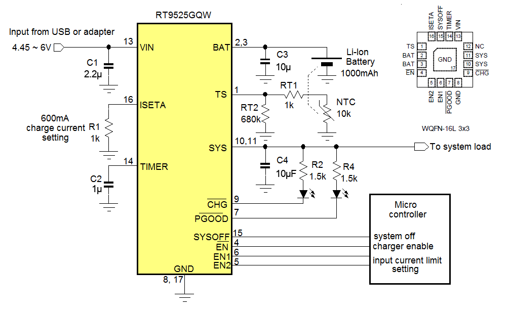
Figure 9. Typical RT9525 charger for small battery powered application with auto power path.
RT9451 is a switching charger with I2C control, which allows flexible selection of charging parameters and system control. Switching topology allows up to 12V input and 4A fast charging current in Buck mode. The switching MOSFETs can also be set in boost mode where a stable 5V with currents up to 1.6A can be supplied from battery to the Vin pin for powering USB-on-the-Go (OTG) devices. RT9451 is often used in systems with larger capacity Li-Ion batteries (> 2Ah), like tablets PC, but it can also be applied in power banks, where the high current OTG function can be used for charging external devices.
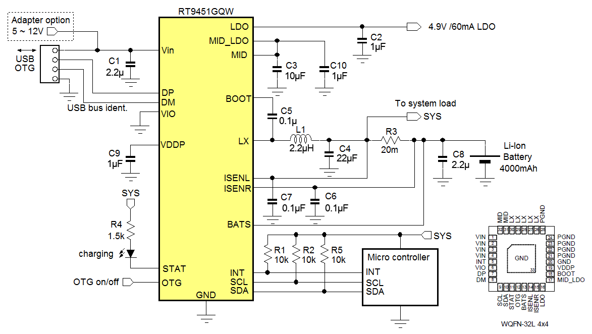
Figure 10. Typical RT9451 application for charging high capacity battery cells.
4. Battery Gauge
In many battery applications it is important to know how much charge is left in the battery. Checking the state of charge (SOC) of Li-Ion cells is often done by coulomb counting method, which measures the battery current over time and determines the SOC from the net increase / decrease in charge. These methods are accurate in theory, but suffer from accumulation errors over time, and the circuit is complicated due to the current sense circuit.
An alternative SOC measurement can be done via dynamic voltage based fuel gauge, which measures the battery voltage over time, and uses the dynamic voltage measurements in combination with a battery model to calculate the relative SOC. This topology does not suffer from error accumulation, and is used in RT9420 and RT9428 battery gauge IC’s. These IC’s are simply connected to the battery terminals, and monitor the battery voltage very accurately over time. They use an internal algorithm to calculate the relative SOC and communicate it back to the host microcontroller via I2C. For best SOC accuracy, the application battery pack needs to be characterized during design stage: Battery specific compensation as well as temperature and charge/discharge effects can then be included in the SOC calculation.
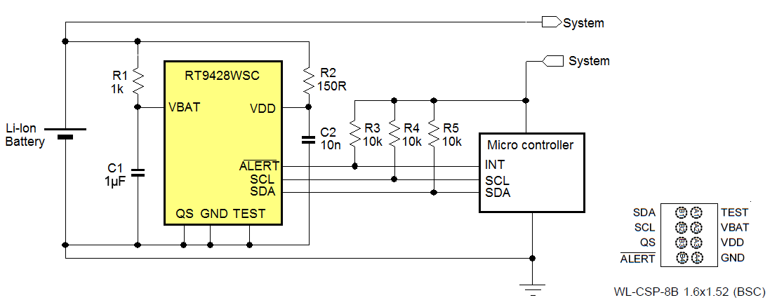
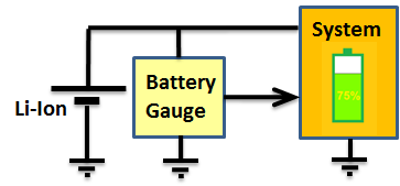
Figure 11. RT9428 battery gauge application
Figure 10 shows the typical application of RT9428. For accurate battery voltage measurement, Kelvin connection to the battery leads is recommended.
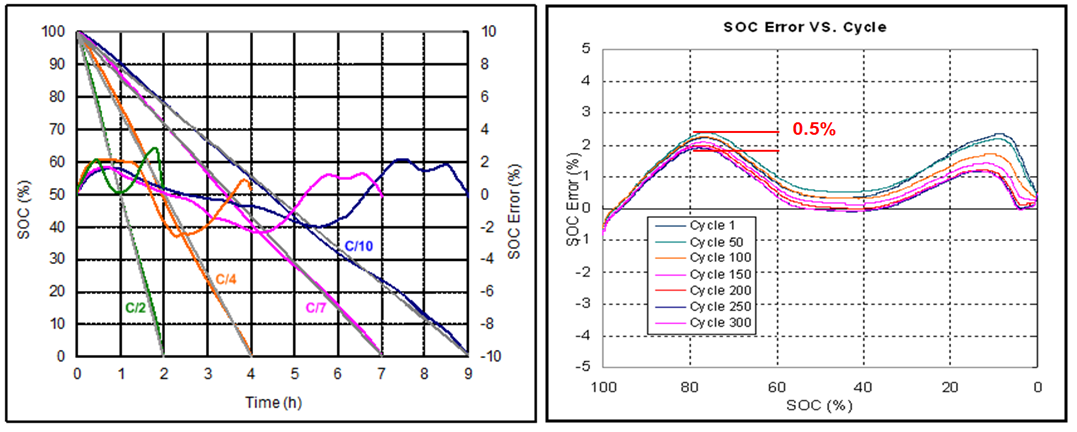
Figure 12. SOC measurement and SOC error at different discharge conditions and over charge/discharge cycles.
RT9428 can achieve good SOC accuracy over various charge/discharge conditions and battery cycles.
5. Summary
Designing applications powered with Li-Ion batteries needs some special attention to make sure that the battery is operated in a safe manner and will have long lifetime. Richtek has a wide range of power management ICs specifically designed for Li-Ion powered applications, which incorporate the functionality to ensure stable and safe operation. Please visit Richtek website at Battery Management Landing Page for more information about Li-Ion application power management ICs.