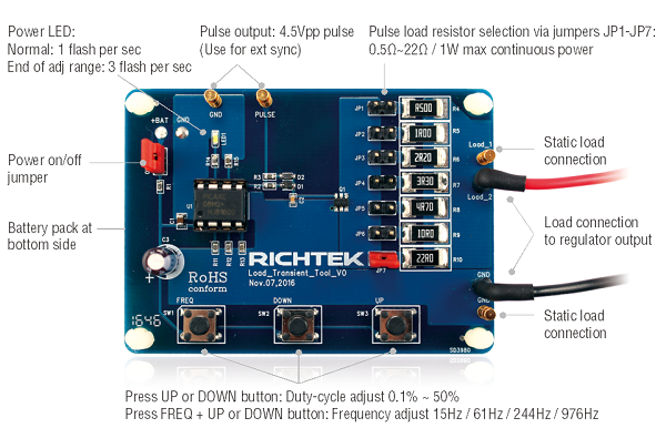
Figure 1: Richtek Load Transient Tool connections and
functions
The Richtek Load Transient Tool contains a micro controller
that switches a MOSFET on and off with a certain duty-cycle. When connected
to a voltage regulator output, the MOSFET switches a load resistor on and off,
thereby creating a fast changing pulse load. The tool can generate very fast
load steps (~500nsec rise/fall times), and can be applied to any voltage regulator
output in your system. My measuring the regulator output voltage during the
fast load step, the regulator control loop behaviour can be observed.
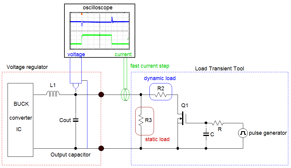
Figure 2: Basic Load Transient measurement method
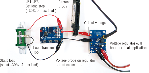
Figure 3: Practical Load Transient Tool measurement setup
A fast load step will excite the system control loop over
a wide frequency range. Control loop instability or under damped response can
be seen as output voltage ringing. This is only valid for CCM (continuous current
mode) operation, so PSM-CCM transitions should be avoided. Always adjust the
static load for CCM operation range during the load step.
Figure 4 shows an example of a poor and a good load step
response of a 3.3V / 3A converter. The example on the left side shows that the
regulator output voltage has severe ringing after a load transient, indicating
that the control loop has marginal stability. In most cases this is related
to the converter feedback loop compensation in combination with the output capacitor
value.
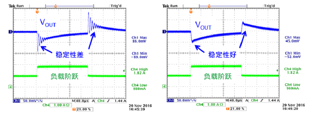
Figure 4: example of poor and good load step response
Besides control loop stability issues, other resonance
effects due to layout parasitic trace inductance, input supply ringing etc.
can also be quickly identified with the fast load transient tool.
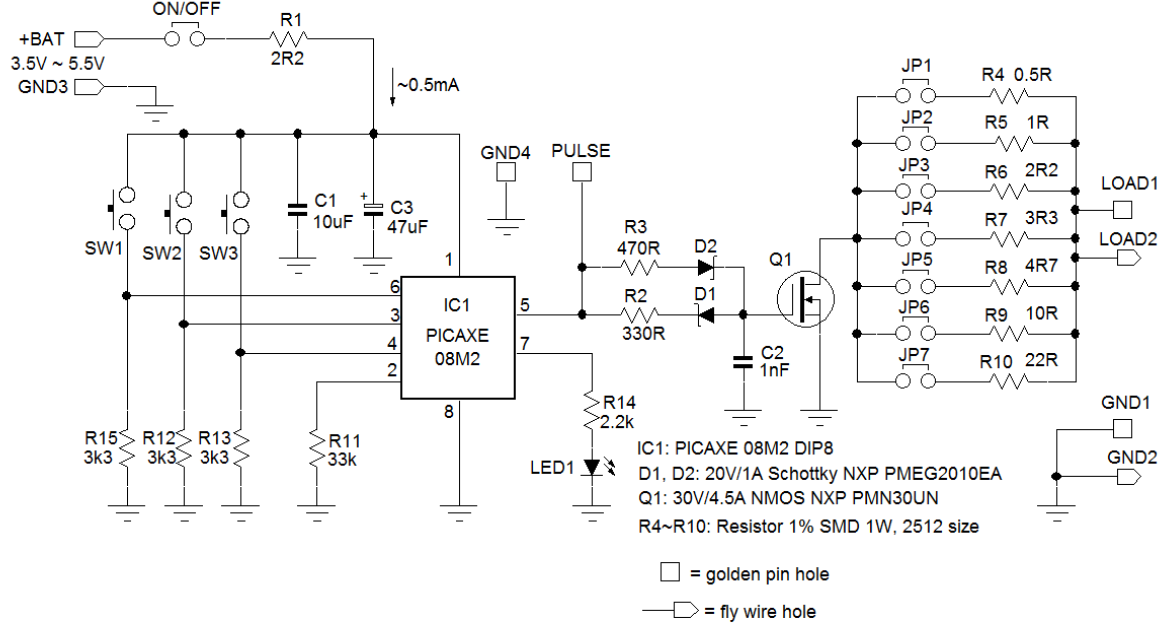
Figure 5: Load Transient Tool schematic
The schematic in figure 5 shows the the micro controller
which drives the MOSFET switch. The MOSFET gate drive is designed to generate
equal switching speeds with ~500nsec rise/fall times. Reducing or removing C2
can increase the switching speed, but the actual load current transient speed
will be mostly determined by the wiring inductance between the tool and the
application. Especially when testing low voltage supplies (< 2V), it may
be necessary to use short, thick wires between the tool and the application
to minimize inductance, see figure 6.
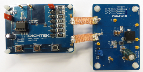
Figure 6: Reducing wire inductance between transient tool
and application for faster load step speed.
The tool consists of a load transient board, an adjustable
power resistor for setting static load and battery pack, see figure 7.
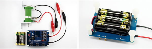
Figure 7: Richtek Fast Load Transient Tool kit.
Guidelines for use:
- Insert 3x1.5V AAA batteries in the battery holder. Please note the correct
polarity.
- Connect the power jumper: Power LED lights for 1 second, and then flashes
once per second. (Default start-up frequency is 244Hz with 5% pulse load
duty-cycle).
- Connect the Load_2 & GND connection to regulator output.
- Connect the adjustable 10Ω power resistor to the static load pins.
Adjust the slider for low level load current to be in CCM mode (or ~30%
of regulator max load).
- Insert the jumper to JP1~JP7 for desired pulse load resistor (suggestion for stability check: VOUT/RLOAD ≈ 30% of maximum converter load)
- Measure the pulse load current in the load wire and observe voltage
regulator output during load transient. Ringing in the voltage waveform
can point to insufficient stability.
- The PULSE output can be connected to scope ext sync. Note that doing
this can create ground loops and the regulator output voltage reading may
be affected.
- The pulse load duty-cycle can be adjusted by pressing UP and DOWN buttons.
The adjustment range is 0.1% ~ 50%. The power LED will flash quickly when
end of adjustment range is reached. Note that the power dissipation in the
pulse load resistors increases when duty-cycle is increased. Do not exceed
1W average power!
- The pulse load frequency can be changed by pressing FREQ + UP or DOWN
buttons together. The frequency adjustment range has 4 steps: 15Hz, 61Hz,
244Hz (default) and 976Hz. The power LED will flash quickly when end of
adjustment range is reached. Duty-cycle is maintained when changing frequency.
- Remove the power jumper to stop the pulse load generator. Static
load will remain.
- Re-insert power jumper will reset pulse load duty-cycle to 5% and frequency
to 244Hz.
For more information on converter loop
stability and load transient testing, please read the application note AN038
“DC/DC
converter testing with Fast Load Transient”