Conducted EMI Reduction by Means of Hybrid Common Chokes
Abstract
EMI suppression solutions come in different combinations of filters, transformer coil arrangements, and even PCB layouts. This application note offers what is called a hybrid common choke, which is a magnetic hybrid consisting of a common-mode choke and a differential-mode choke. A hybrid common choke preserves the characteristic of high impedance of the common-mode choke. Its high leakage inductance can be used as the differential-mode inductance. It not only features a smaller size to reduce the filter cost, but also provides engineers with a convenient solution to conducted EMI problems.
1. Principles and Functions of a
Hybrid Common Choke
In a typical single-stage EMI filter circuit, as in Figure 1, a common-mode noise filter (LCM、CY1 and CY2) and a differential-mode noise filter (LDM、CX1 and CX2), in the form of LC filters, attenuate common-mode and differential-mode noises respectively. A common-mode choke is usually made of highly permeable Mn-Zn ferrites, and the inductance can be as high as 1~50mH. A common-mode choke can be seen in Figure 2. Due to the winding polarity arrangement, even though load currents flowing through the two sets of coils respectively, the magnetic fluxes inside the core can cancel out. Henceforth, core saturation will not occur. The commonly used core types are toroid type, UU type (UU-9.8、UU-10.5 etc.), ET type, and UT type, as shown in Figure 3. To obtain high common-mode inductances, the two sets of coils should be coupled as good as possible. Therefore, toroid cores of high construction cost, or one-piece cores of ET type and UT type have often been used.
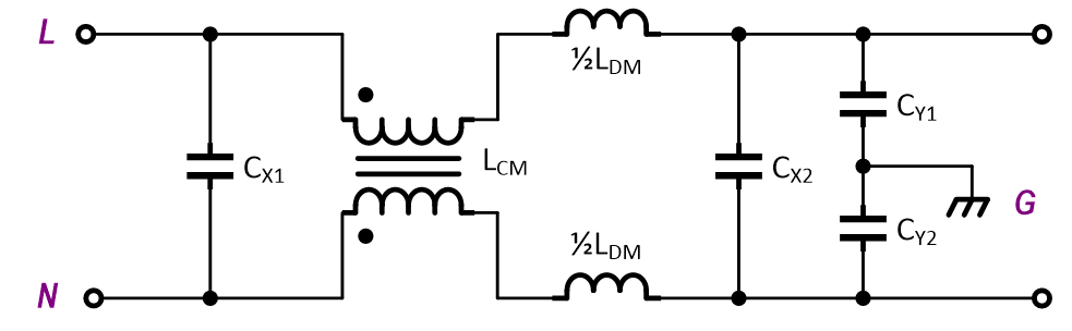
Figure 1. A typical EMI filer configuration
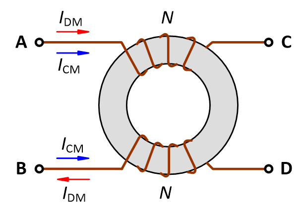
Figure 2. A common-mode choke
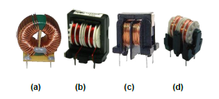
Figure 3. Commonly used core types: (a) Toroid type (b) ET type (c) UU type (d) UT type
From the operating principles and the equivalent circuit of a common mode choke, as in Figure 4, it can be seen that though the two sets of coils are coupled well, there still exists a leakage inductance, which results from leakage magnetic fluxes. The leakage inductance is equivalently in series connection in the circuit, and acts as a differential-mode inductance. Therefore, the leakage inductance of a common-mode choke can be used for a differential-mode filter. However, due to the mechanical structures of common mode chokes, as in Figure 3, their leakage inductances are quite small, only around a few μH to 100μH. The only way to obtain higher leakage inductances is by increasing the coil turns. In this way, the coil wire must be thinner, given the same core, and in turn the rms current will be decreased. To counteract this, the core must be enlarged, which results in larger filters and higher cost. Some applications require high common-mode inductances. It is, however, not for filtering common-mode noises, but for obtaining the high parasitic leakage inductances, intended for differential-mode filters. Such practice is often unknown to engineers.
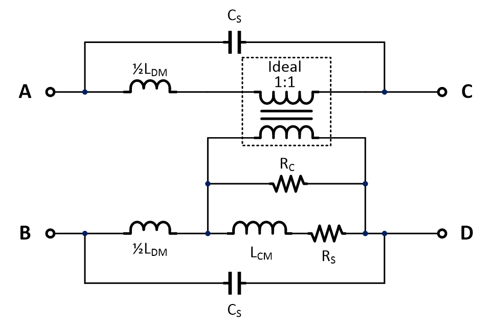
Figure 4. An equivalent model of a common-mode choke
To increase the leakage inductance of a common-mode choke, a unique core structure and coil winding is employed. Such a common-mode choke is called an integrated common-mode choke or a hybrid common-mode choke, as shown in Figure 5. This choke structure retains high common-mode inductances to filter out common-mode noises, and can have as high as hundreds of μH differential-mode inductances, from the leakage inductances. Combined with proper X capacitors, they can effectively filter out low/mid-band (150kHz ~ 3MHz) differential-mode noises. By experiment, hybrid common-mode chokes prove to make excellent filters. And their greatest advantages, low cost and small size, make them outperform their counterparts.
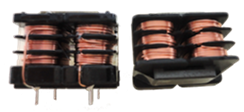
Figure 5. Vertical and horizontal hybrid common-mode chokes
2. Major Electrical Parameters
A hybrid common choke not only keeps the characteristics of a common-mode choke but also has those of a differential-mode choke. In addition to the general specifications for common-mode chokes and differential-mode chokes, the following parameters are also specified.
(1) Common-mode Impedance, ZCM: Compared to the high-frequency equivalent resistance of a Line Impedance Stabilization Network (25Ω for common-mode), the higher the common-mode impedances, the better filters they make. In addition to core materials, the ways to wind the coils (e.g. number of coils) may affect high-frequency impedances more. Figure 6 shows the set-up for measuring common-mode impedances. Figure 7 shows the common-mode impedance characteristics of the ASU-1200 series. Since stray capacitance, CS, exists among the coil layers, it will become capacitive at high frequency. Therefore, the smaller the CS, the better.
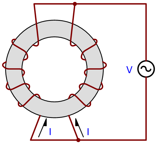
Figure 6. The measurement set-up for common-mode impedances
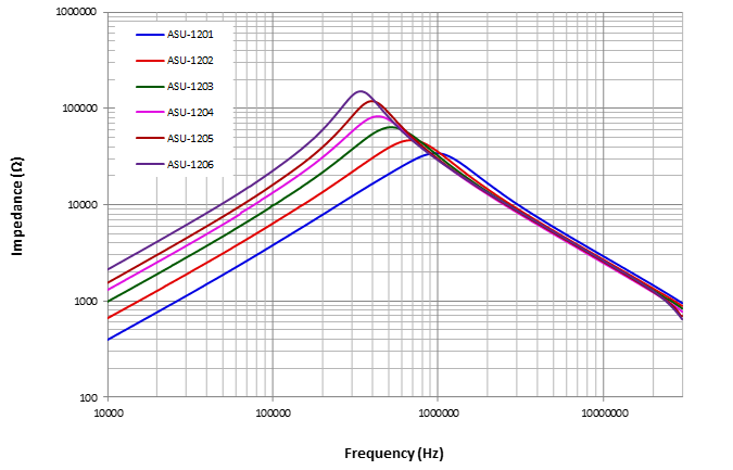
Figure 7. The common-mode impedance characteristics of the ASU-1200 series
(2) Common-mode Inductance, LCM: Conventionally, common-mode inductances are characterized by an externally added voltage (VOSC) and by the frequency in use. Characterizing common-mode inductances with VOSC = 1Vac @100kHz usually have more stable results, though it may vary with core materials.
(3) Differential-mode Impedance, ZDM: Similarly, the set-up for measuring equivalent differential-mode impedances is shown in Figure 8. The differential-mode impedance characteristics plot, as seen in Figure 9, can be used to describe the differential-mode filter performance. Compared to the LISN equivalent resistance, 100Ω, higher differential-mode impedances are better. At high frequency, it still becomes capacitive. However, with great enough impedance, it can still make a good filter.
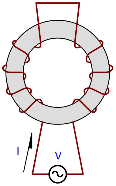
Figure 8. The measurement set-up for differential-mode impedances
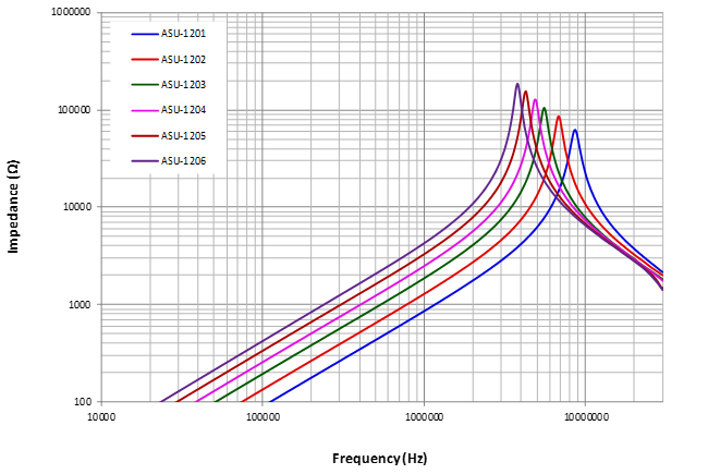
Figure 9. The differential-mode impedance characteristics of the ASU-1200 series
(4) Differential-mode Inductance, LDM: Likewise, differential-mode inductances can be specified with VOSC = 1Vac @100kHz. In practical applications, differential-mode inductances of a hybrid common choke should be greater than 100μH to effectively filter out differential-mode noises, combined with X capacitors.
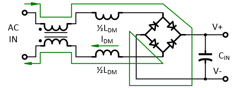
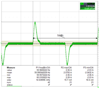
(5) Differential-Mode Saturation Current, Isat: As said previously, because load currents flow through the equivalent differential-mode inductors, the differential-mode inductances should not be saturated at the peak load currents; otherwise, the filter performance will be degraded. Figure 10 depicts a bridge rectifier filter circuit and the input current waveform. It is required that at peak load currents, the differential-mode inductances will not decrease because of core saturation. Conventionally, Isat is defined as the current at which the inductance drops by 20% (compared to the value at no DC bias current).
(a)
(b)
Figure 10. (a) A full-bridge filter circuit, (b) the input current waveform
(6) Root Mean Square Current, Irms: Equivalently, this rating is to define wire width. The input current waveform of Figure 10, Irms, is not high, which can usually be estimated by that the minimum input voltage divides twice the output power. For example, with a full input-voltage range 25W power adapter, its Irms can be calculated as 2 x 25W / 90Vac = 0.55A.
Table 1: Electrical parameters of the ASU-1200 series
|
LCM (mH) ±20%
|
LDM (μH) ±10%
|
Isat (A)
|
Irms (A)
|
|
ASU-1201
|
4.0
|
143
|
3.2
|
1.00
|
|
ASU-1202
|
6.0
|
220
|
2.9
|
0.80
|
|
ASU-1203
|
9.0
|
310
|
2.4
|
0.75
|
|
ASU-1204
|
12.0
|
410
|
2.2
|
0.75
|
|
ASU-1205
|
16.0
|
530
|
1.9
|
0.60
|
|
ASU-1206
|
20.0
|
670
|
1.8
|
0.55
|
3. Application Circuits
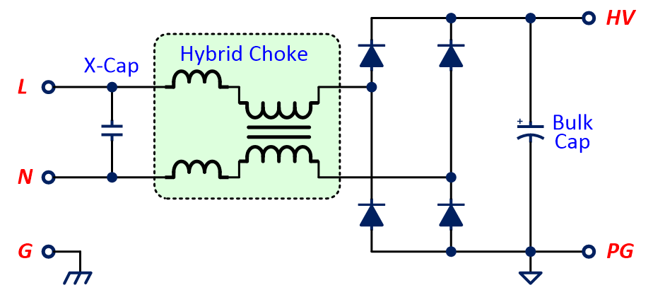
Simply put, a hybrid common choke integrates a conventional common-mode choke and a (or two) differential-mode choke(s). For different applications, EMI engineers must decide on common-mode chokes, differential-mode chokes, and also differential-mode saturation currents, Isat, and root mean square current Irms. The ASU-1200 series hybrid common chokes are suitable for the applications of 25W-50W Flyback circuits or <120W PFC circuits. Figure 11 presents the examples of two flyback circuits, using a hybrid common choke.
(a)
(b)
Figure 11. Two flyback circuits with hybrid common chokes (a) conventional filter with an X capacitor (b) a conventional filter with an X capacitor to the output of a bridge rectifier
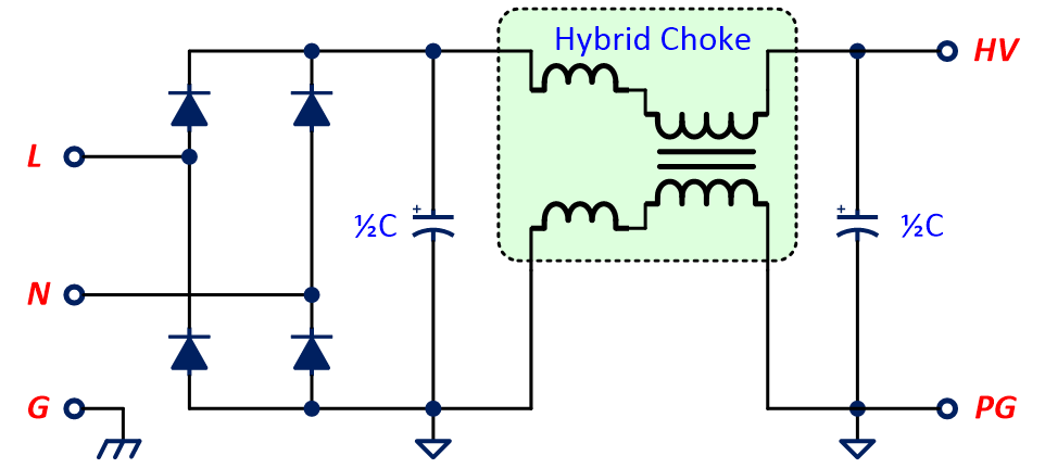
Figure 12 shows that a hybrid common choke is used in an active filter for power factor correction (PFC) in boundary conduction mode.
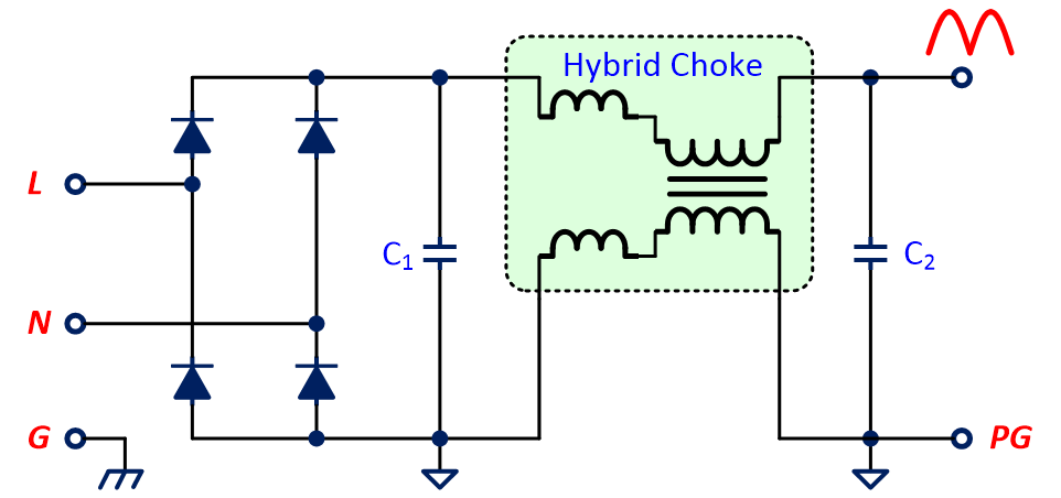
Figure 12. The application circuit of a hybrid common choke in a PFC circuit
Figure 13 to Figure 15 show the EMI performance of a 24W (12V/2A) offline flyback power supply using an ASU-1203 hybrid common choke. It can be clearly seen that not only common-mode noises are effectively reduced by such hybrid common choke, but also differential-mode noises by its differential-mode inductance. Overall, the EMI performances show that noises can be attenuated by about 30dB at low/mid-band frequency with an ASU-1203.
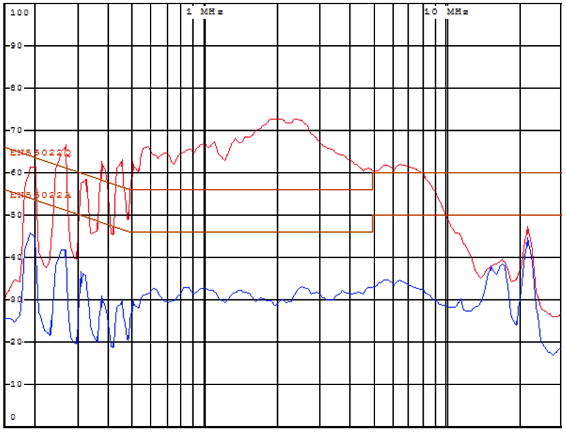
Figure 13. Common-mode noise attenuation (The blue line depicts the measurement of common-mode noises with an ASU-1203)
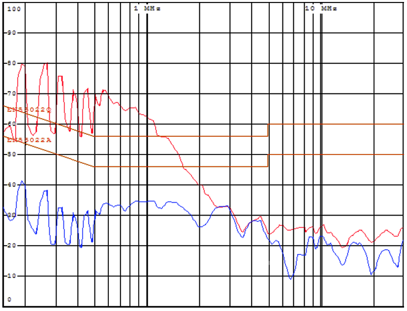
Figure 14. Differential-mode noise attenuation (The blue line depicts the measurement of differential-mode noises with an ASU-1203)
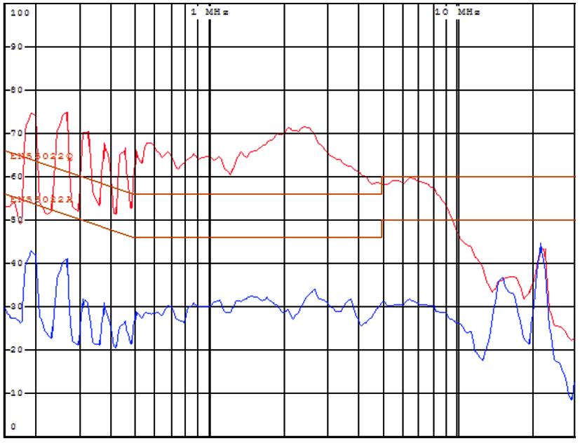
Figure 15. Total noise attenuation (The blue line shows the measurement of total noises with an ASU-1203)