1.
Overview
The operation of the heart can reveal many valuable information about the human body, including its healthy lifestyle, emotional state and the early onset of heart disease. In traditional medical equipment, monitoring heart rate and heart activity is by connecting the electrodes to body, then measuring the electrical signal triggered by the heart tissue. The heart rate has a pressure wave that passes through the blood vessel, which changes the diameter of the vessel slightly. Photoplethysmography (PPG) is an optical technology to measure this slightly vessel changes. Therefore, it can obtain information on heart function without measuring bioelectrical signals. PPG is mainly used to measure blood oxygen saturation (SpO2), but it also provides cardiac function information without bioelectrical signal measurement. With the help of PPG technology, the heart rate monitor can be integrated into wearable devices such as watches or wrist bands for continuous detection applications.
2.
Vitalsign
Signal Monitoring : ECG vs. PPG
and PTT
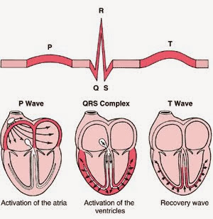
Electrocardiography (ECG or EKG) is a kind of the chest in time record the electro vitalsign activity of the heart. It can record the potential transmission of the heart by pasting the electrode on the skin surface of the human body. The results of electrocardiogram are usually shown in wave form, including P wave, QRS wave group and T wave. P wave represents the atrial contraction, QRS wave group is ventricular systolic, T wave is ventricular diastolic. The time interval between the R wave and R wave is represented the heart rate. The shorter RR interval represents the heart rate is lower. Measuring ECG signals often involves attaching sensors to multiple parts of the body, and up to 10 electrodes can be connected between the chest and limbs.
Source : healthy-ageing
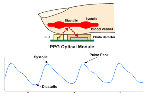
Photoplethysmography (PPG) is a noninvasive method to detect the changes of blood volume in living tissue by photoelectricity. When a certain wavelength of light reaches the skin surface of the finger, the contraction and expansion of blood vessels will affect the transmission of light (for example, in transmitted PPG, the light passing through the finger tip) at each heartbeat. Or the reflection of light (in the reflection PPG, for example, from near the surface of the wrist). The light is attenuated when it passes through the skin tissue and then bounces back to the light sensor. Muscle, bone, veins and other basic organization under skin is the constant on the absorption of light. But blood is different, because the artery blood flow, so the absorption of light can also change. When we converts light into electrical signals, it is because of a change in the absorption of light arteries and other tissues absorb light basically remain unchanged, the signal can be divided into DC and AC signal. The AC signal can be extracted to represent the characteristics of blood flow.
Below is a comparison of PPG signal and ECG signal.
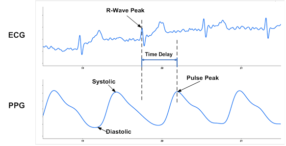
According to the vitalsign characteristics of the PPG and ECG, we can find that the peak value of ECG is from ventricular contraction, while the peak value of PPG is caused by vascular contraction. Therefore, we can get the transmission time of blood from the heart to the measurement site, i.e., Pulse wave to Pulse Transit Time (PTT). The speed of pulse wave transmission is directly related to blood pressure. When blood pressure is high, pulse wave transmission is fast, and vice versa. In this way, Pulse Transmission Time (PTT) is obtain through that ECG and the PPG, and the pulse wave transmission speed can be derived from the personal body parameter (such as height and weight). The systolic pressure and diastolic pressure in each stroke of the human body can be estimated by the derived characteristic equation to achieve a non-invasive continuous blood pressure measurement.
3.
The
Challenge of Vitalsign Signal Monitoring
ECG Measurement Challenges
The ECG electrodes are normally placed on both sides of the heart and attached to the skin. It can be used to record the changes in electrical signals over time. ECG measurement faces many challenges : the 50Hz to 60Hz coupling interference from ECG main power source is much stronger than the heart signal; On the other hand, the contact impedance mismatch between the body skin and sensor electrodes will lead to greater signal deviation and reduce the common-mode inhibition ability. In addition, we also have to solve the problem of the interaction and the interference from the electromagnetic source. Some important design considerations in such applications include common-mode rejection, input offset voltage, offset voltage drift, output swing and amplifier noise, as described below :
- Common Mode Rejection
As mentioned above, the electrodes placed on the patient's skin may have a dc voltage of about hundreds of millivolts, while the voltage of the wanted signal is usually less than one millivolt. The instrumentation amplifier configuration is very suitable for this case, which will eliminate any signals from the input common mode (from the electrodes or any common mode noise, such as 60Hz interference), while at the same time enlarging the desired electrocardiogram signal. In this case, it is important to consider the common-mode rejection ability of the amplifier circuit, not only for DC signals, but also for crossover frequencies, especially at 50Hz or 60Hz from power lines.
- Input Offset Voltage
and Offset Voltage Drift
Since the useful voltage is quite small, the amplifier needs to provide enough gain to improve the resolution of the following detection circuit. This application requires high gain, so the offset voltage of the amplifier is very important. Any offset voltage generated by the amplifier is multiplied by the circuit gain. For example, if the heart contracts to produce 1mV on a specified electrode of the skin, and if the gain of the amplifier circuit is set to 1000, the ideal output of the amplifier circuit will be 1V. If the input offset voltage of the amplifier is 100µV, however, an error of 100mV at the output is produced (10% of the occupied signal). The error will be proportional to the gain of the amplifier. The voltage deviation of the amplifier is the source of the error, and the margin of error can get even bigger with the drift of the offset voltage.
As with all electronic components, the characteristics of the amplifier vary over time and temperature, as so the voltage offset. However, such error sources can be greatly reduced by selecting low drift amplifiers (such as amplifiers using an auto-zero calibration topology) or periodically performing system calibration, thereby correcting the offset and drift operational amplifiers.
- Output Swing
In the previous example, 1mV voltage change at the electrode would produce 1V voltage change on the output of the amplifier circuit. For a 5-volt single-power supply system, this means that the amplifier circuit can accurately detect 0 to 5mV voltage, and the amplifier needs to be able to output swings to the lowest and highest power rail. On the contrary, if the amplifier doesn't support rail to rail output swing, the dynamic range of the voltage will become smaller. It will not be able to correctly detect the complete input signal. Therefore, the dynamic range of the detection circuit is limited and the accurate detection cannot be made.
- Amplifier Noise
Another important parameter to consider when evaluating amplifiers for such applications is amplifier noise. It is important to note that the amplifier noise may not on frequency constant, especially in the 1/f noise can become the main noise source under low frequency; In ECG applications, desired signal bandwidth is usually from dc to 100Hz, so 1/f noise is still a source of error.
PPG Measurement Challenges
The main challenge to measuring PPG is interference from ambient light and motion. The dc errors generated by sunlight are relatively easy to eliminate, but the light emitted by both fluorescent and energy-saving lamps has a frequency component that can cause ac errors. Motion also interferes with the optical system. It may not be a problem when the optical heart rate monitor is used for sleep research, but if you wear it during exercise, it will be very difficult to eliminate the motion image. The relative movement between the optical sensor (LED and photo-detector) and the skin reduces the sensitivity of the optical signal.
In addition, the frequency component of exercise may be considered a heart rate measurement. Therefore, the motion must be measured and compensated. The more closely the equipment is attached to the body, the less this effect is, but it is almost impossible to mechanically eliminate this effect. Motion may be measured using a variety of methods, one of which is the optical method, i.e. the use of multiple LED wavelengths. The common-mode signal represents exercise, while the differential signal is used to detect heart rate. However, it is preferable to use a true motion sensor. The sensor may not only accurately measure the movement applied to the wearable device, but may also be used to provide other functions such as tracking activity, calculating the number of steps, or starting a certain application when a particular g value is detected.
4.
ECG Measurement Circuit
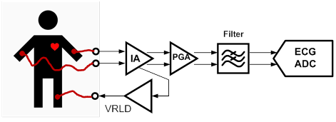
A typical ECG device usually realized by analog front-end circuits for signal amplification, filtering, and then data acquisition through an ADC. When using low resolution (16-bit) ADC, the signal needs to be significantly amplified (usually 100 to 200 times) to reach the necessary resolution. Using high resolution (24-bits) Σ - DADC, signal only need 4 to 5 times for a modest gain. Therefore, the second gain stage amplifier for dc offset removal can be eliminated. It will reduce the chip size and die cost. Σ - DADC method will also retain the signal across the whole frequency band, and provide sufficient flexibility for data post-processing.
Instrument
Amplifier (IA)
The main task of the instrument amplifier (IA) is to suppress the common mode signals (typically 50Hz/60Hz interference). ECG applications require 90dB, or even higher, common-mode rejection ratio (CMRR) to suppress the 50Hz/60Hz signal from the power source. Even with a IA having a high CMRR, a mismatch between different ECG electrodes or a skin contact impedance not only produces offset drift, but also results in CMRR below a desired level. Impedance mismatch is mainly caused by physical contact between electrodes and skin, perspiration and muscle movement. Besides, the gain of IA also need to be considered. It is necessary to set the proper gain of IA to avoid clipping or saturation the signal. It's also important for IA's input impedance, because ECG measures the weak signal. IA with high input impedance is recommended, because low input impedance leads to large signal attenuation.
The 2nd Stage Gain Amplifier (PGA)
After noise and interference are eliminated by IA and filter, the second stage amplification is carried out to provide additional gain to achieve the input range of ADC. Some designs have added a notch filter to further suppress 50Hz/60Hz from power line.
Low Pass and Anti-Aliasing Filter (Filter)
The low-pass filter is used to suppress high frequency interference and also acts as an anti-aliasing Filter, which prevents any signal greater than Nyquist or 1/2 of the sampling frequency to prevent ADC aliasing.
In order to further reduce the input common-mode signal, the ECG design usually introduces the "right leg driver" (VRLD), which drives the anti-phase common-mode signal back to the human body. To make sure patient safety, an operational amplifier and a current limiting resistor are used to ensure that a very weak signal source is being driven to the human body. The shielding circuit is also employed to reduce the noise coupling from ECG probes to carry signals.
5.
PPG Measurement Circuit
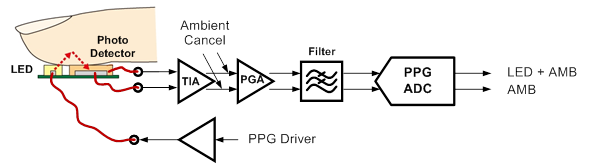
The measurement circuit of PPG includes : LED in the optical transmission drive system, and measure the reflecting signal from photodiode. The goal is to measure the maximum photocurrent for a given LED current (current transmission ratio). The input and reception signals of the photoelectric diode are amplified and filtered through a trans-impedence amplifier (TIA) and then obtained by an ADC.
Ambient light interference is a big problem, especially when the light is modulated, like a solid-state lighting system with leds or energy-saving lights. In order to get a good signal response, the effect of ambient light interference is reduced through digital signal processing. This is a key function that can effectively suppress the external light interference.
6.
RT1025 Product
Information
The RT1025 is an integrated AFE solution for Heart-Rate monitoring and measurements. The RT1025 integrates low noise voltage and current sensing channels and is capable of sensing ECG (Electrocardiography) and PPG (Photoplethysmography) simultaneously. The RT1025 have > 100dB dynamic range and can sense pulses accurately by detecting the heart’s electric signals. The sampling rates of the high-precision voltage and current sensing channels in the RT1025 are configurable between 64 to 4kHz. The RT1025solution need only few discrete components and is easy to use for low-power medical ECG/PPG, sports, and fitness applications. With high levels of integration and high-precision voltage and current sensing channels, the RT1025 solution is suitable for scalable medical instrumentation systems. The RT1025 is available in a 3.1mm x 3.4mm, 41-Ball, 0.4mm pitch, WL-CSP package. The RT1025 conforms to IEC 60601-2-27 and China YY1079 specification, is suitable for the medical level ECG/PPG, fitness, and the application of wearable products.
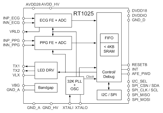
The RT1025 supports the reading of samples and device status upon interrupt or via polling. It contains 4kB SRAM for data buffering. The device is internally clocked to offer high-precision clock with external crystal. The flexible timing control enable the users to control the PPG device timing for different application and to power down the device for power saving. The device can connect as a slave to either a SPI or I2C master.

RT1025
Product Features
- ECG Channel Features
Supports Two-Electrode (2E) Mode and Right Leg Drive (RLD) Mode
Low Noise PGA and High Resolution ADC
Input Impedance : 125M to 500MΩ at Two-Electrode Mode and > 1GΩ at Right Leg Drive Mode
Low Input-Referred Noise : 0.67μVrms (64Hz ODR, Gain = 12)
Dynamic Range : 110dB at Gain = 6
CMRR > 85dB at 60Hz
Data rate : 64SPS to 4k SPS
- PPG Channel Features
Flexible Timing Control and Support Dynamic Power Down
TX Supports H-bridge and Push/Pull Mode
TX LED Current Range : 10 / 25 / 35 / 50 / 65 / 75 / 90 / 105mA, each with 8-bit Current Resolution
Input Maximum Current Range : 0.5 to 50µA
Input Maximum Capacitance : 1nF
Input-Referred Noise : 50pArms at 5µA Input Current
CMRR > 80dB at 60Hz
PGA Gain : 1 to 6V/V
Ambient DAC1/DAC2 Range : 1 to 6µA
- Others
2-in-1 Bio-Sensing AFE (Voltage/Current)
Built-In Heartbeat Interval Estimation
Integrates an Oscillator to offer High-Precision Clock with External Crystal
Support I2C and SPI I/F for MCU
On-Chip SRAM for Data Buffering
Ultra-Low Power Consumption
Operating Temperature Range : –20°C to 65°C
Small 3.1mmx3.4mm, 41-Ball, 0.4mm Pitch, and WL-CSP Package
RoHS Compliant and Halogen Free
ECG/PPG
AFE Evaluation Board
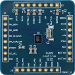
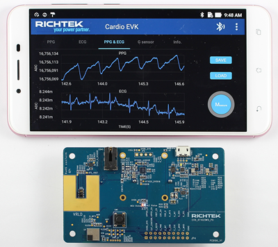
Richtek Technology develops an ECG/PPG AFE Daughter Board (PCB107_V1) and Cardioid Evaluation Board (PCB106_V1) with Android app (Cardio EVK) to evaluate the RT1025 performance. For more information, please find the related datasheet or application notes from the Richtek website http://www.richtek.com.
|
|
|
|
Daughter Board (PCB107_V1)
|
Cardioid Evaluation Board (PCB106_V1)
|
7.
Summary
The RT1025 is an analog front-end chip that can meet ECG/PPG measurement requirements at the same time and provide good performance without increasing cost. Simultaneous capture of ECG/PPG signals can improve the accuracy of PTT blood pressure calculation. It helps to reduce your development budget, shorten the design phase, save the area of the circuit board and reduce the number of elements in the system. The RT1025 also improves the performance and reliability of your product.