Introduction to Richtek VCORE Solutions
1.
Introduction
VCORE regulators are used to provide the power supply for the CPU core and graphics (GPU) core in computing applications like Desktop PC, Notebook PC, Server, Industrial PC, etc. The requirements for these supplies are quite different from standard POL regulators: CPU and GPU rails have extremely fast load changes, require Dynamic Voltage Positioning with high accuracy, require Load Line, can switch between several states of power saving and provide a variety of parameter sensing and monitoring. These systems make use of a serial Bus interface between the CPU and the voltage regulator, where the CPU will request different supply operating conditions based on CPU loading and operation modes. This application note explains the VCORE regulator application and the specific regulator operating conditions related to CPU & GPU commands. Richtek has a wide portfolio of Intel and AMD VCORE solutions. To be able to select the right part for a specific computing platform, a selection guide for Richtek VCORE solutions vs. Intel / AMD platforms is provided in chapter 7.
2.
Basic Vcore regulator applications
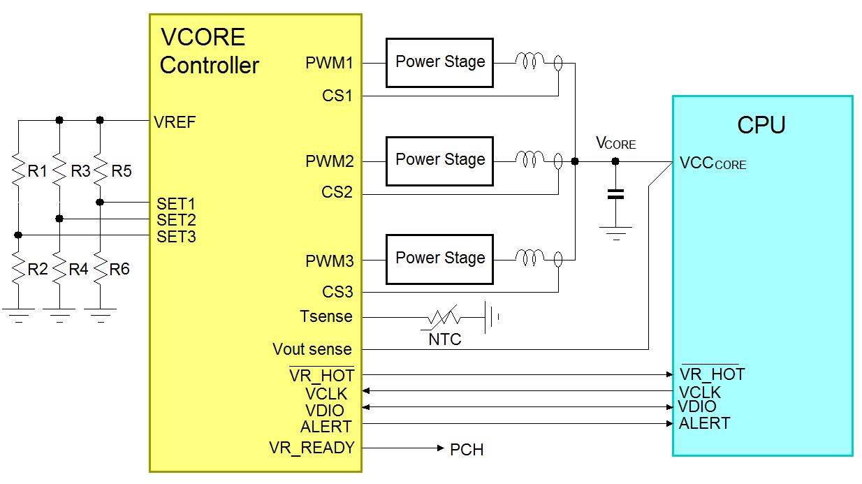
Figure 1: Basic Vcore regulator application
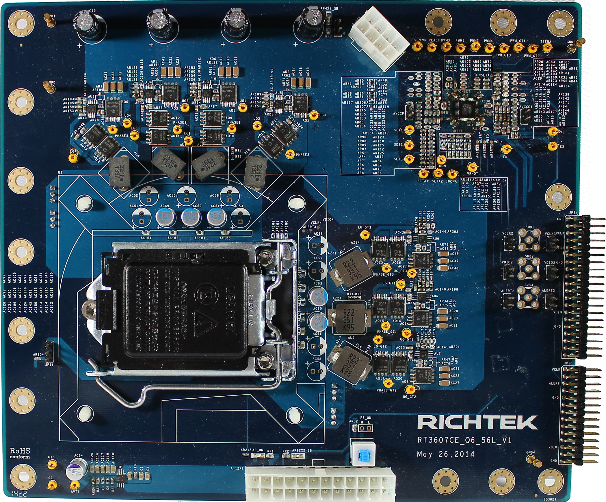
Figure 1 shows a basic Richtek VCORE regulator application for driving an Intel CPU power rail. VCORE regulators normally consist of a controller and external power stage, due to the high current levels of CPU power rails. Low power CPUs can use single phase buck converters, but the more powerful CPU’s will require multi-phase buck converters. In the above example the buck power stage uses 3 phases, which for desktop PC applications is good for around 70A thermal design current (TDC). The VCORE output voltage is sensed at specific sense points in the CPU socket and this sense voltage is used as feedback for the regulator.
There are several communication lines between CPU and the voltage regulator: a serial bus with clock and data lines and one or two warning lines for notifying the CPU of specific events at regulator side. The CPU can send specific commands to the voltage regulator via the serial bus communication, like VCORE voltage change or to set specific power states. The CPU can also request information from the voltage regulator like actual current consumption or thermal operating condition of the power stage. One of the selection criteria of VCORE regulators is the serial communication protocol: For Intel platforms this can be VR12.1, VR12.5, IMVP8 or IMVP9, and the AMD platforms serial communication is called SVI or SVI2.
VCORE regulators have many user programmable parameters, which can be set based on CPU voltage and performance requirements, protection levels and to fine tune regulator response. Due to the large amount of parameters and programmable values, several resistor dividers are used to set these parameters.
Accurate current sense of each phase is an important feature of VCORE regulators: it is needed for reporting the total current consumption to the CPU, but is also used to maintain good current sharing between the phases, for closed loop control, setting a load line and over-current protection.
Thermal conditions are monitored via NTC’s placed close to the power stage components, and the thermal conditions can be read by the CPU or the regulator can initiate an alert when a certain temperature is exceeded.
In many computing platforms, the CPU core and graphics core are integrated in one Accelerated Processing Unit (APU) chip. VCORE voltage regulators designed for APUs will therefore have two buck converter stages, one for the Core and one for the Graphics rail. The APU graphics rail will normally consume less current than the core rail, so it often uses less phases. Figure 2 shows an example of a APU power solution. The communication between APU and voltage regulator uses the same serial bus. Each serial command will include an address designator for addressing the Core or Graphics part of the regulator. Most other functions will be similar for core and graphics converter.
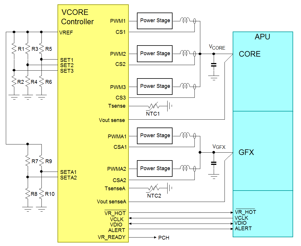
Figure 2: APU Vcore regulator application
3.
VCORE regulator design aspects
The Buck controller design of VCORE regulators is quite different from normal Buck regulators: This is because the VCORE supply has to fulfill many special requirements:
Dynamic voltage change during operation: Dynamic Voltage Identification (DVID):
Average power consumption and thermal management are important aspects of VCORE design: CPU’s operate better at higher supply voltage, but this also increases their power consumption and temperature. For a specific CPU to run stable at a certain speed, a certain VID CORE voltage value is specified. To optimize system performance without excessive power consumption, the CPU supply voltage is changed dynamically depending on operating conditions: In idle mode where CPU speed is lower, the CPU supply voltage is lowered to reduce power consumption, but when CPU activity suddenly needs to increase, the CPU supply is quickly increased to ensure stable CPU performance in computing intensive conditions. VID adjustment is very dynamic, and the converter has to be able to quickly and precisely adjust the core voltage with adjustable slew-rate based on the received VID command. Figure 3 shows a dynamic VID behavior: In the plot on the left, the CPU will send the DVID command (from 1.8V to 1.2V, slowly ramping down slow in this case), the regulator will then ramp down the output voltage with the requested speed. When the output voltage is at the target value, the regulator will pull low the ALERT pin, to warn the CPU, which in turn will send a clear Alert command. INTEL CPUs can request slow or fast VID slew rate: The plot on the right side shows a fast up DVID with slew-rate of 52mV/µsec, matching Intel specification.
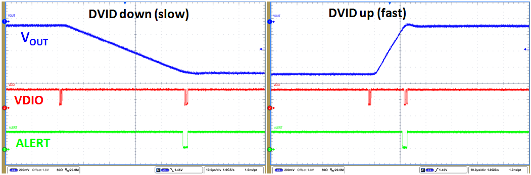
Figure 3: DVID behavior
Programmable Load Line (Voltage Droop) via Richtek G-NAVPTM:
An ideal regulated supply rail with high loop gain will keep the average output voltage constant regardless the load current, (figure 4 left side). But during a sudden load increase, the output voltage will momentarily dip, and when the load is suddenly removed, the output voltage will show a short peak. The output voltage including tolerances, ripple and load transient dips and peaks must stay above the CPU minimum voltage to avoid system hang, and must stay below the CPU maximum voltage to avoid CPU damage. A certain amount of output capacitance is needed to absorb the load transient dips and peaks. Adding a load line (or voltage droop) will result in the output voltage dropping when the load current is increased as shown in figure 4 middle picture. Then a positive VID offset can be added as shown in figure 4 right side.

Figure 4: Load line characteristics
Although this seems counterproductive to good voltage regulation, it actually increases the headroom for load transients; at light load the CPU voltage is now higher than the nominal value and a voltage dip due to sudden load increase has less chance to reach the minimum CPU voltage limit. At high load, the output voltage is now lower than the nominal value, and a voltage peak due to sudden load release has more headroom before reaching the CPU maximum limit. Adding voltage droop therefore relaxes the requirements on load transient response and makes better used of the total CPU tolerance window, making it possible to reduce the amount of bulk capacitance on the output rail.
Figure 5 shows an example of a VCORE voltage under a fast 70A peak-peak load transient. The plot on the left side has no voltage droop (zero load line) and the total voltage fluctuation due to dips and peaks is quite excessive. The plot on the right side includes 2mΩ load line and 80mV VID offset. At 70App transient, the voltage droop is 70A*2mΩ = 140mV. The total voltage fluctuation is now reduced, reducing the risk of CPU crash or damage. The lower core voltage during high load also reduces CPU temperature.
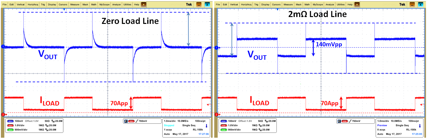
Figure 5: Load transient without and with load line
Voltage droop is also called Adaptive Voltage Positioning (AVP). A maximum load line value will be specified for each CPU platform.
The Richtek VCORE regulators make use of a current mode (CM) - Constant On Time (COT) control loop for the basic voltage regulation. The simplified block diagram is shown in figure 6.
|
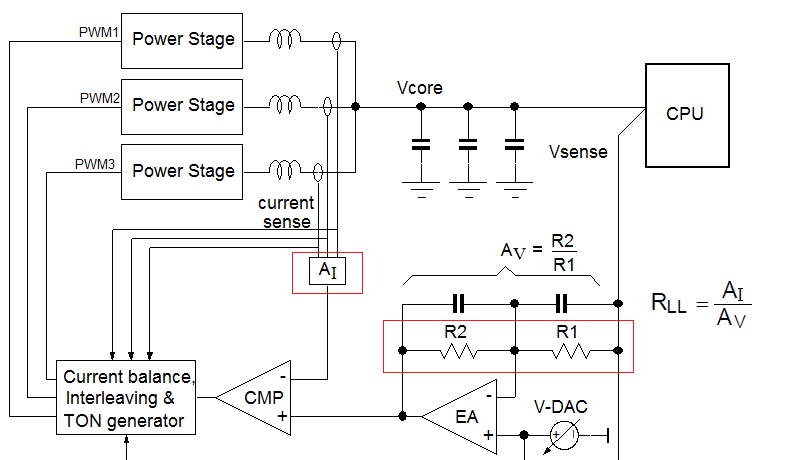
Figure 6: Control loop with G-NAVP
|
For easy implementation a load line in the converter, the Richtek VCORE control loop uses a propriety technology called Green-Native AVP (G-NAVPTM) which applies a current mode control system with an error amplifier having an adjustable lower DC gain, which is different from traditional control systems which use very high gain error amplifiers. The low gain error amplifier will introduce a natural output voltage reduction at higher load current.
|
This method makes it easy to implement a defined load line, as the load line value is simply defined by the current sense gain AI and error amplifier gain AV. The reduced gain of the error amplifier also simplifies the error amplifier compensation method, which can be a simple one zero one pole design.
Improved dynamic load regulation with Richtek Quick Response (QR):
CPU and GPU operating conditions are extremely dynamic: Web browsing for example does not require a lot of CPU activity, but opening a large Excel file or opening an HD video will result in a sudden increase the CPU or GPU activity. The CPU power consumption will show very dynamic behavior. 80% load current steps with rise times of 100nsec are common, resulting in huge dI/dt transients. The control loop of the VCORE voltage regulator has to be well designed to keep up with these dynamic load variations and keep the output voltage within certain limits to avoid CPU crash. Load transient response is therefore one of the most critical design criteria for VCORE regulators.
To improve the load transient handling capability, Richtek VCORE controllers apply an additional QR network to the CM-COT control loop as shown in figure 7.
|
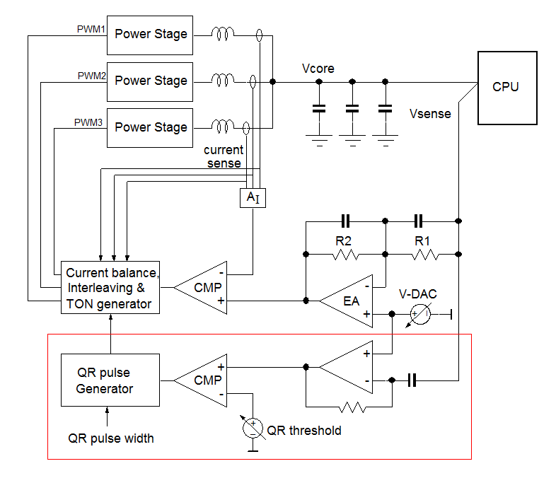
Figure 7: Control LOOP with Additional QR network
|
The output voltage is sensed by an error amplifier that compares the sensed voltage with the internal target output voltage DAC. The COMP output of the error amplifier is compared with the sum of the current sense signals of the different phases. In steady state, a constant TON is triggered each time the COMP signal reaches the valley of the current sense. The converter controls the
PWM duty-cycle by changing the off-time. When the output voltage drops due to a sudden load current increase, the error amplifier COMP voltage will increase, and successive TON pulses are generated.
|
This control method has some limitations when dealing with sudden load steps:
1. The bandwidth limit of the error amplifier slows down the reaction speed to a load transient
2. The fixed ON time can only deliver a certain amount of extra current.
3. The phase interleaving mechanism will delay the activation of subsequent phases during a load transient.
To increase the response speed and energy transfer during load transient, Richtek VCORE controllers include a separate Quick Response (QR) loop (shown in the red block of figure 7). This loop will quickly detect when the output voltage suddenly drops, and will force all phases to generate a simultaneous ON pulse. The Quick Response detection threshold and Quick Response ON time are programmable via pin setting. This makes it possible to fine tune the power stage behavior to the load step and minimize output voltage undershoot during large load transients. Figure 8 shows a 3-phase converter step response without QR (relying only on the error amplifier loop) and with QR enabled (where the QR network temporarily bypasses the error amplifier loop). It can be clearly seen in figure 8 right side that with QR enabled, the converter reaction time is faster, and the simultaneous activation of all phases with an increased QR ON time pulse will increase the short-term energy transfer, thereby greatly reducing the output voltage undershoot.
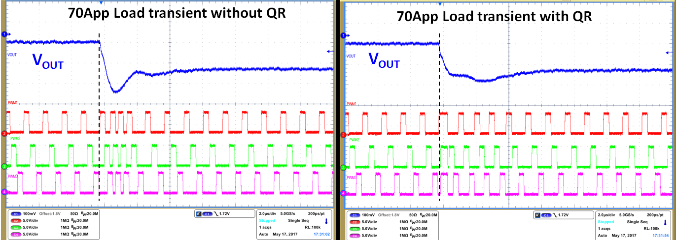
Figure 8: Load transient without and with QR
Higher Accuracy output voltage and better system efficiency via Richtek CCRCOTTM topology
The CPU voltage needs to be well controlled over a wide output voltage adjustment range. This requires high accuracy DAC tolerance, down to 0.5%. At such low voltage tolerance levels, the output ripple variation needs to be taken into regard as well. The output voltage ripple in VCORE regulators is mostly determined by the inductor peak to peak current ripple due to output capacitor ESR.
In constant frequency Buck converters, the inductor peak to peak current ripple will increase when either the input voltage increases (i.e. when plugging your adapter in your notebook PC) or output voltage increases (i.e. with VID changes). The inductor current ripple is given by the formula: 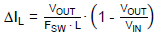 .
.
Constant frequency VCORE regulator designs will therefore show different output voltage ripple at different operating conditions.
In Constant TON (COT) buck converters, the current ripple is given by 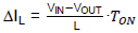
The inductor current ripple in standard fixed ON time converters will change at different operating conditions, resulting in varying output voltage ripple and reduced output voltage accuracy. Richtek VCORE controllers use a special CCRCOT (Constant Current Ripple Constant On Time) technology that adjusts TON based on input voltage and output voltage settings to keep the inductor current ripple (and thus output voltage ripple) constant over the entire input and output voltage range, thereby achieving better voltage accuracy, as illustrated in figure 9 right side.
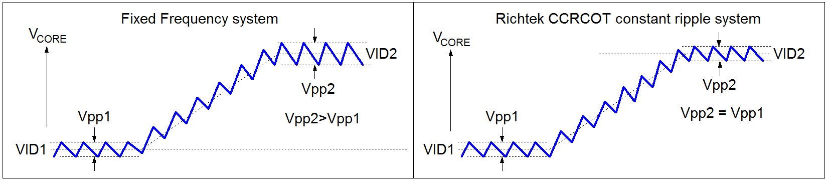
Figure 9: VID change with fixed frequency and CCR-COT system
Another benefit of CCRCOT systems is that switching frequency automatically reduces at lower input voltage and output voltage. The lower switching frequency will help improve system efficiency. Since VCORE VID voltage is lowered at lower power modes, CCRCOT helps to improve the system light load efficiency.
Similarly, in portable systems that can run from adapter or battery, the battery operation switching frequency is automatically reduced since battery voltage is lower than adapter voltage, thereby reducing switching losses and improving battery life. For CCRCOT converters, the maximum switching frequency should be designed at the highest performance mode, which is highest VID voltage, highest input voltage and highest load.
|
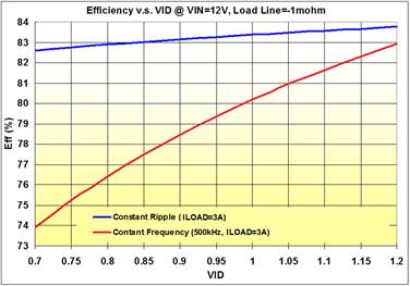
Figure 10: Efficiency of fixed frequency vs. CCRCOT system
|
Figure 10 shows the efficiency comparison between a 500kHz fixed frequency system and a constant ripple system. The constant ripple system frequency was set at 500kHz at the same maximum 25A load and maximum VID as used in the fixed frequency system. As can be seen, the efficiency of a CCRCOT system (blue line) will be much better at lower load and lower VID voltage compared to a fixed frequency system.
|
Power save modes:
Depending on the operation condition, CPUs can set the VCORE regulator in various power save modes. Intel CPUs distinguish several power states: PS0, PS1, PS2, PS3. In PS0 mode all phases run together for full power capability. A PS1 command from the CPU will keep only one phase active and all other phases are disabled to reduce switching losses. In PS2 mode, the remaining active phase is switched from force-PWM mode into Diode Emulation Mode (DEM) which lowers the switching frequency at light load to further reduce switching losses. In PS3, the VID core voltage is lowered and the regulator is set in low quiescent current mode for lowest power loss. Figure 11 below shows the transition from PS0 to PS1 and PS0 to PS2. Since COT converters regulate the off time, DEM mode is easy to achieve by disabling the low side MOSFET when zero inductor current is detected.
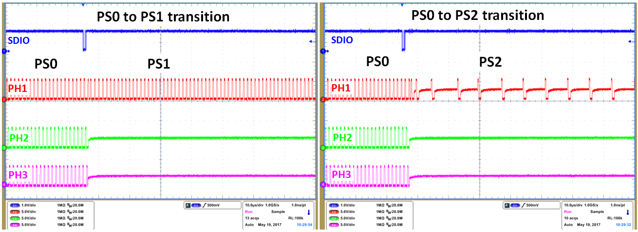
Figure 11: Vcore during power state transitions
Single or multi-phase Step-down regulator:
The current consumption of VCORE supply rails depends on CPU’s and GPU’s type and the end application. CPU applications that require relatively low computing power (like small industrial automation applications) will generally consume less than 10W. In these applications, mostly single phase step-down converters are used. High-end PCs consume much higher power, sometimes exceeding 100W. Since the CPU core voltage is low the current is very high, and can reach values exceeding 100A. This requires multi-phase buck converters, where the number of phases depends on the maximum current of the VCORE supply rail. For desktop PC applications, generally 20A ~ 25A thermal design current (TDC) per phase is used, but for smaller portable applications the maximum current per phase maybe chosen lower due to power component size or thermal limitations. Richtek VCORE regulators for each platform will have a wide range of products to choose from: from single phase to multi-phase, with or without embedded MOSFET drivers. Figure 12 shows an example of Richtek VCORE regulators for Intel Coffee Lake (CFL) S-line: This line has several different APU’s with different power levels. Based on performance, thermal, space and layout consideration, the user can select Richtek VCORE controller parts based on number of phases and embedded drivers or external driver versions for the core and graphics rails.
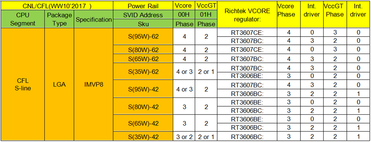
Figure 12: Richtek vcore regulators for different CPU types in intel COFFEE LAKE S-line
4.
Richtek PMIC solutions
VCORE controllers normally only provide the power for Core and Graphics rails. But some smaller APU’s include circuits for other functions as well like I/O power and peripheral control hub (PCH) processing, making them more like System on Chip (SoC). These kind of devices are often used in small form-factor applications like Netbook, Tablet or Industrial PCs, and higher integration of the power stages may be desirable. Richtek also offers several integrated PMIC power solutions for these platforms. The block diagrams below show three solutions for the popular Intel AtomTM based Braswell Platform:
|
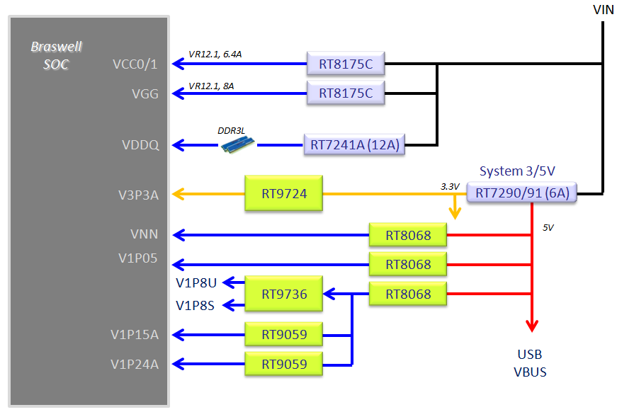
Figure 13: Braswell discrete power solution
|
Figure 13 shows a discrete solution: The Core and graphics rails are powered by separate buck regulators, and the memory VDDQ rail is powered by a 12A DDR converter solution. The lower current rails are powered by separate buck converters or linear regulators. To obtain the correct power-up sequence normally an embedded controller is needed. This solution has relatively high part count, and since each device consumes power, also in standby, the total quiescent current is relatively high.
|
|
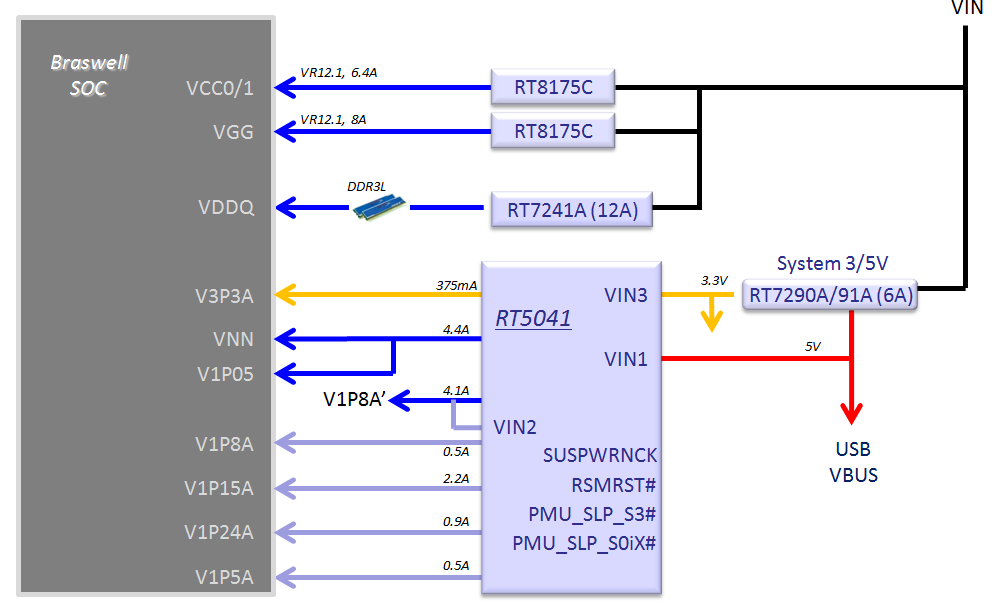
Figure 14: Braswell multi-output IC power solution
|
Figure 14 shows a power solution with higher integration: all lower power rails have been integrated into one chip. This has the advantage of lower component count and reduced board space, but it also makes it possible to achieve lower overall quiescent current in standby modes, thereby extending battery life in portable applications. This solution also takes care of correct power sequencing. and uses CMCOT topology for fast transient response. The RT5041 pinning is optimized to match the Braswell SoC pinning for optimal layout routing.
|
|
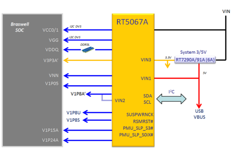
Figure 15: Braswell PMIC power solution
|
Figure 15 shows the highest possible integrated power solution for Braswell, using RT5067A PMIC to take care of all power rails. The low current rails use integrated ultrafast ACOT buck power stages, while the high current rails VCC, VGG and VDDQ use external MOSFET drivers and MOSFETs, which allows more optimal layout of the high current power stages. The serial control between SoC and PMIC uses I2C instead of the VR12.1
serial protocol. The I2C communication option can be selected via BIOS. Besides lower component count and board space reduction, this solution also offers the lowest standby quiescent current for prolonged battery life.
|
5.
VCORE with embedded driver vs.
external driver
Many Richtek VCORE buck controllers come with versions having embedded MOSFET drivers. Embedded drivers will of course reduce the application size and reduce total component count. But external drivers sometimes do have some advantages: When the layout is such that there is some distance between the buck controller and the power stage, it may be better to choose external drivers. This will avoid having to route the MOSFET gate drive signals over long traces, which could worsen signal integrity.
|
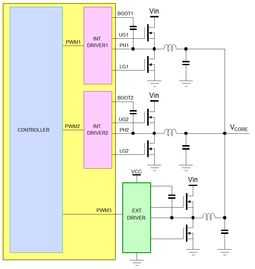
Figure 16: Embedded and external MOSFET driver
|
Figure 16 shows an example of a 3-phase Buck controller with two embedded drivers and one external driver. This configuration provides some flexibility: for systems which don’t need 3 phases, the 3rd phase can be disabled, and the circuit can use the 2 embedded driver phases to power the circuit.
For circuits that need 3 phases, the controller can be placed in such a way that the two embedded drivers + power stages are close to each other. The 3rd phase can route the PWM3 signal over a longer trace to the external driver which is placed close to its power stage as well.
|
Figure 17 shows an example of an APU regulator with 3 phases / 2 embedded drivers for the core rail and 2 phases / 1 embedded driver for GFX rail. The regulator IC pinning with respect to the APU chip is optimized for shortest routing of the embedded drivers to power stages, while the power stages are at the far corners of the APU use external MOSFET drivers.
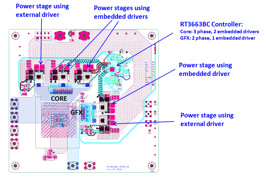
Figure 17: VCORE regulator layout with embedded and external MOSFET drivers
6.
Richtek VCORE design tools
and evaluation kits
Due to the complexity of VCORE regulators, the design of the peripheral components can be quite time consuming. To aid the designer and reduce design time, Richtek provides Excel based design tools for each VCORE regulator part.
The design tool will have a Parameter_Core input tab, where the particular platform and CPU rail requirements can be entered. The detailed external component values can then be calculated in the Loop_Core tab, like Ton setting, Current sense network, Load line, EA compensation, SETx pin bias, thermal compensation and protections. For APU regulators, there will be separate tabs for CORE and GFX sections.
Figure 18 shows a design tool example of an IMVP8 APU for Intel Caffee Lake platforms.
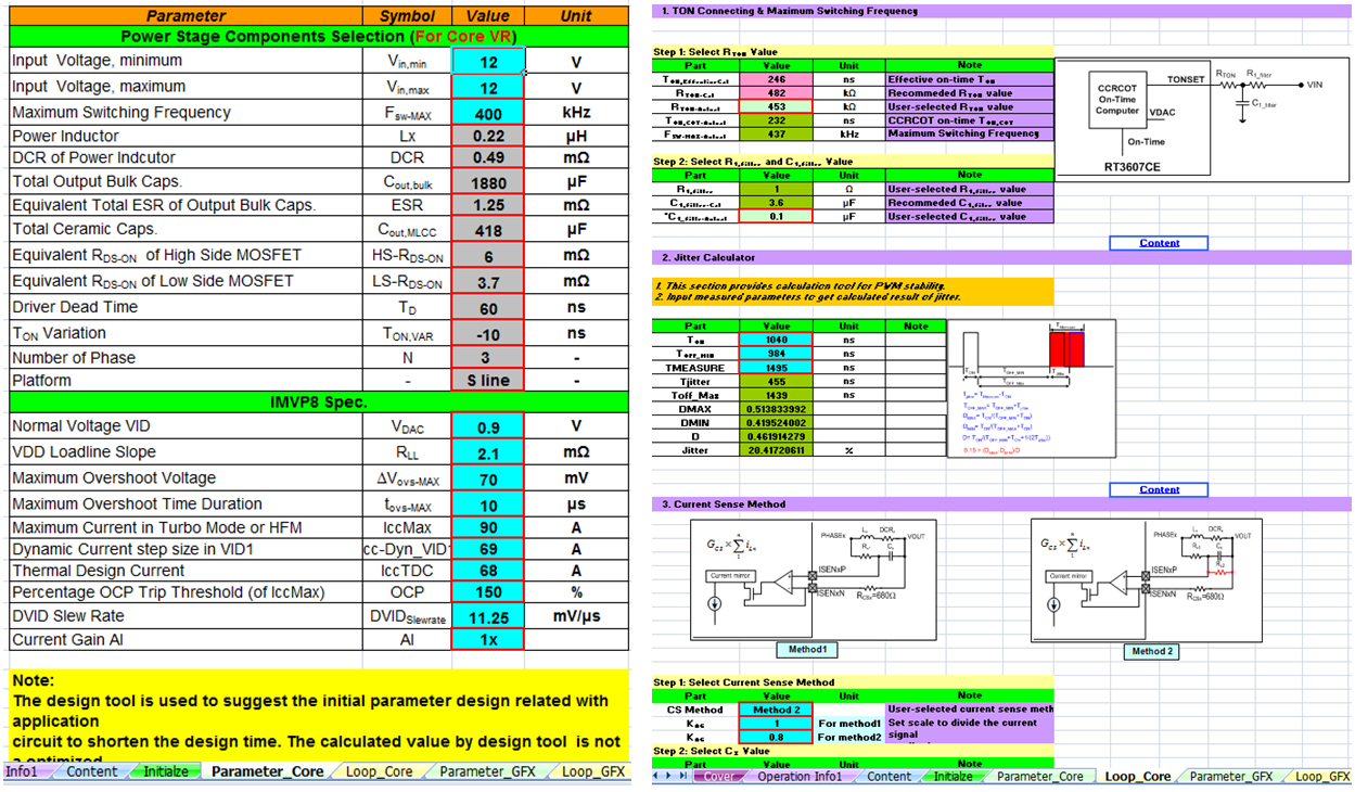
Figure 18: Richtek Vcore regulator design tool
Evaluation boards are available with layout matched to actual CPU sockets. Richtek VCORE solutions are fully tested to fulfill Intel or AMD test plan requirements. It is highly recommended to follow the evaluation board key component selection of output capacitors and inductors, as these are critical in meeting the VCORE rail requirements.
|
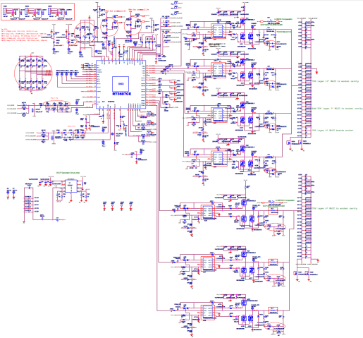
Figure 19: Richtek VCORE evaluation board
|
|
7. Richtek VCORE SOLUTION selection criteria
Richtek has a wide range of VCORE regulator parts for INTEL and AMD platforms. Figure 20 shows an overview.
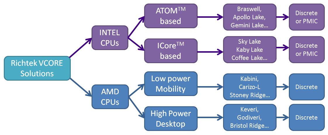
Figure 20: RICHTEK VCORE OVERVIEW
INTEL CPU VCORE regulators
For Intel parts the selection can be divided into two segments: Intel ATOMTM based parts and Intel iCORETM based parts.
ATOM based parts are for portable, small size and low power applications like Net book, Tablet and Industrial PCs. Platform names are Braswell, Apollo Lake and Gemini Lake.
iCORE based CPUs are higher performance lines used in applications like Notebook PC and desktop PC. Platform names are Sky Lake, Kaby Lake and Coffee Lake.
Intel CPUs of different generations use different serial interface protocols: The older Braswell CPUs use VR12.1, while newer generations use IMVP8TM or IMVP9TM. Some ATOM based platforms can also use I2C serial communication.
You can find Richtek VCORE parts for INTEL CPUs by entering CPU specification, platform names and sockets on the VCORE selection page. You can also find system block diagrams of different Intel platforms on the Intel VCORE Solutions page. For a full overview of Richtek VCORE solutions please download the Richtek VCORE product selection list.
AMD CPU VCORE regulators
AMD CPUs can be similarly divided into low power (mobility applications) and higher performance parts.
The low power mobility range have platform names like Kabini, Carizo-L, Stoney Ridge, Raven.
The higher power desktop applications have platform names like Keveri, Godiveri, Bristol Ridge, Summit Ridge.
Besides platform name, CPU socket type is also specified, like FT3, FP4, FP5, FM2+, AM4.
AMD CPU’s use a serial interface called SVI2.
You can find Richtek VCORE parts for AMD CPUs by entering CPU specification, platform names and sockets on the VCORE selection page. For a full overview of Richtek VCORE solutions please download the Richtek VCORE product selection list.
Cannot find a VCORE regulator part?
Due to the fact that Richtek VCORE parts are developed in cooperation with INTEL and AMD some information will not be shown on the Richtek website due to confidentiality reasons. If you would like more information on specific Richtek VCORE regulator parts or are looking for VCORE regulators for specific CPU platforms which are not shown on the Richtek website, please contact your nearest Richtek sales office for more information.