Car Battery Cold Crank Waveform Generator
Abstract
For testing automotive pre-converters, testing with dynamic changing input voltage is mandatory to make sure the system can work correctly during car battery voltage changes like during cold cranking. It is not difficult to build a car battery cold crank voltage generator by using an Arduino and a high current CCM buck converter. This report describes the requirements and how to successfully build such a generator using simple means.
1.
Introduction
During the development of automotive applications that run from the car battery, the circuit designer will
need to test the application with various battery voltage profiles as described in the ISO 16750-2 standard. Especially the car battery cold-cranking waveform can be critical for the correct operation of the application, due to the fact that during this event, the battery voltage drops very fast, down to very low levels.
Generally, programmable power supplies are used as test generator for these kind of tests. However, it is also possible to build a powerful battery voltage profile simulation generator by using an Arduino Nano MCU board in combination with a high current buck converter like the Richtek RT8131BGQW. In this report, the design, programming and operation of the self-build Car Battery Cold-Crank Waveform Generator is presented.
2.
Design Considerations
For testing automotive pre-converters, the ISO 16750-2 standard is used for testing the application input voltage fluctuations. In this example, we will discuss how to generate the battery cold cranking waveform as described in the ISO standard.
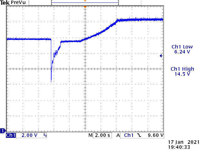
Figure 1
Figure 1 shows an actual measurement of a car battery cold crank waveform which was taken during wintertime around -5 degrees C car outside temperature. It can be seen that due to the cold, the initial car battery voltage is already lower than 12V and it drops to 6.24V during the cold crank. Depending on the battery condition and other circuit loading, the battery voltage can drop more or less. After the engine starts, the generator will start charging the battery and the voltage rises to around 14.5V.
The ISO 16750 standard will describe the cold crank battery voltage drop as following:
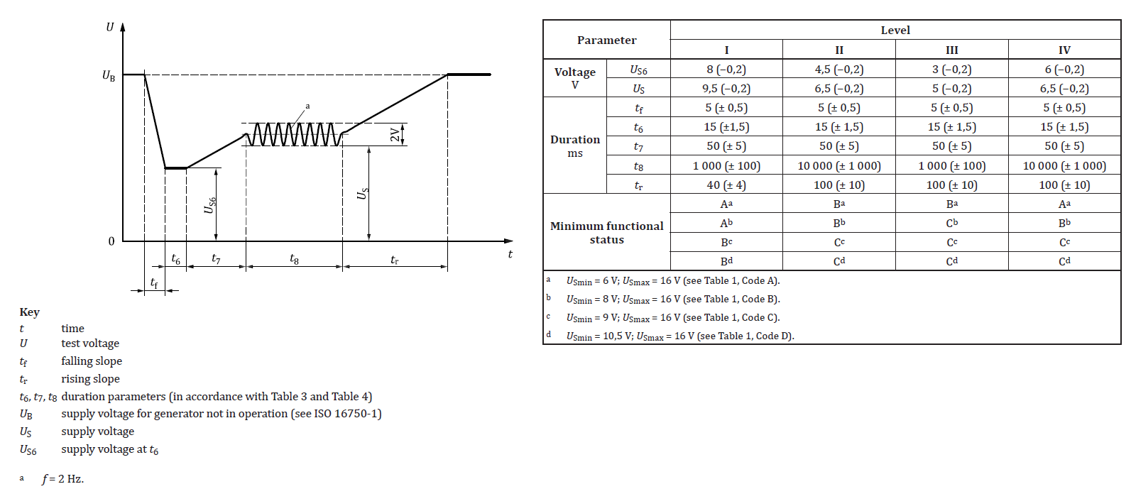
Figure 2
The typical fall time from start is 5msec, and the voltage can drop to different levels. Then it rises to an intermediate level followed by some voltage oscillation during the time the engine is cranking. Then it moves back to the initial voltage level.
A test generator should be able to generate a similar waveform, and should have an easily adjustable voltage modulation from the initial level, in order to check the application behavior at different voltage drop and recovery behavior.
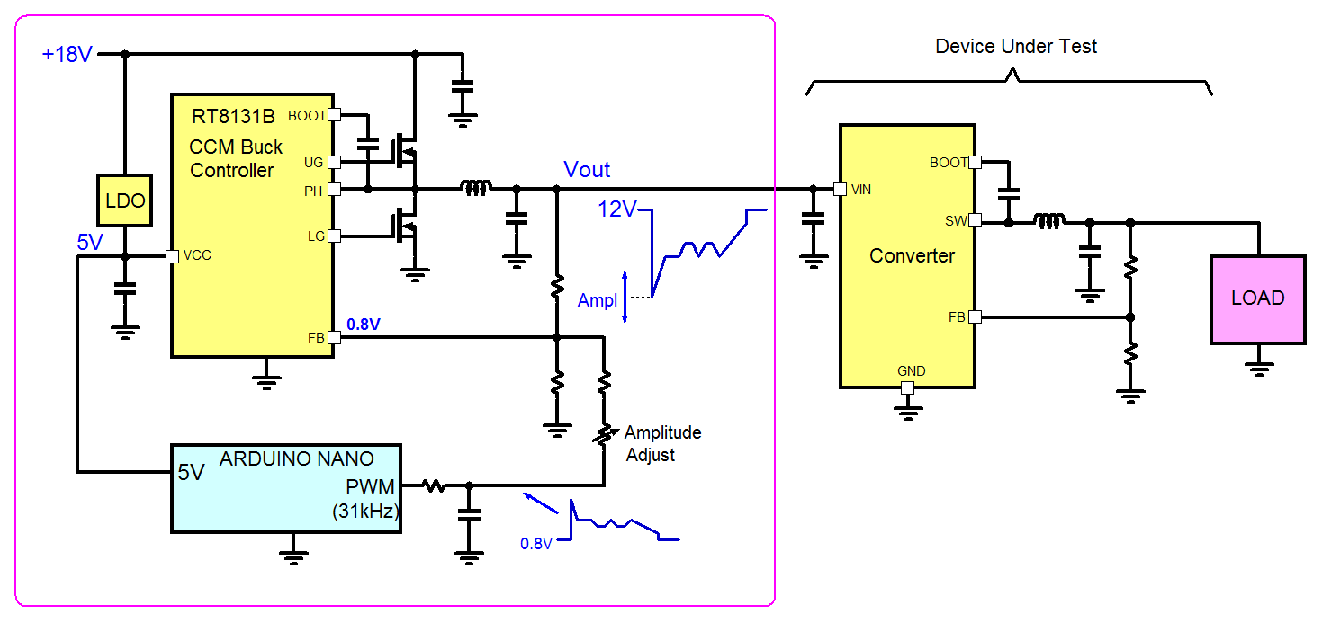
Figure 3
The basic car battery cold crank voltage profile generator
is shown in figure 3. It consists of an Arduino Nano MCU board which is
programmed to provide a changing PWM output which is the inverse of the
cold-crank waveform. This PWM waveform is then filtered, to obtain a voltage
that follows the PWM changes. This voltage is then used to inject a current into
the feedback network of a CCM high current buck converter. The modulation level
of the injection current can be adjusted via a variable resistor. The more current is injected into the feedback network, the lower the Buck converter output will drop. The output of the buck converter can be used to test various car application pre-converter applications, and the high current capability and CCM operation allows fast changing output voltages and load conditions.
3.
Actual hardware design of the cold crank voltage
generator
For the Buck converter, the RT8131BGQW CCM Buck controller is used. The application schematic is shown in figure 4.
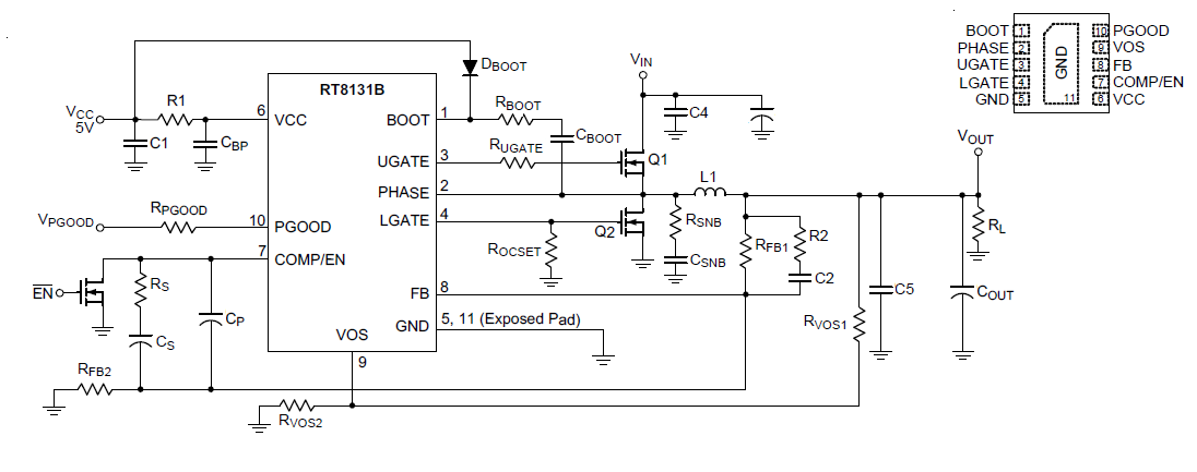
Figure 4
RT8131BGQW is a single phase synchronous voltage mode buck controller that can support input voltage from 5.5V to 26.5V and requires a separate 5V VCC for the internal control circuits and MOSFET gate drivers. It has programmable over-current protection and separately controllable over-voltage protection window via the VOS pin. The CCM operation allows both high current source and sink capability, which is required for fast changing output voltage modulation. The circuit will be designed for 12V typical output voltage. The compensation network can be designed using Richtek voltage mode compensation network design tool. The over-current protection will be set at a high level, to make sure the converter is able to source and sink high current pulses that will happen when driving external devices with large input capacitors.
The final RT8131B 12V step-down application is shown in figure 5.
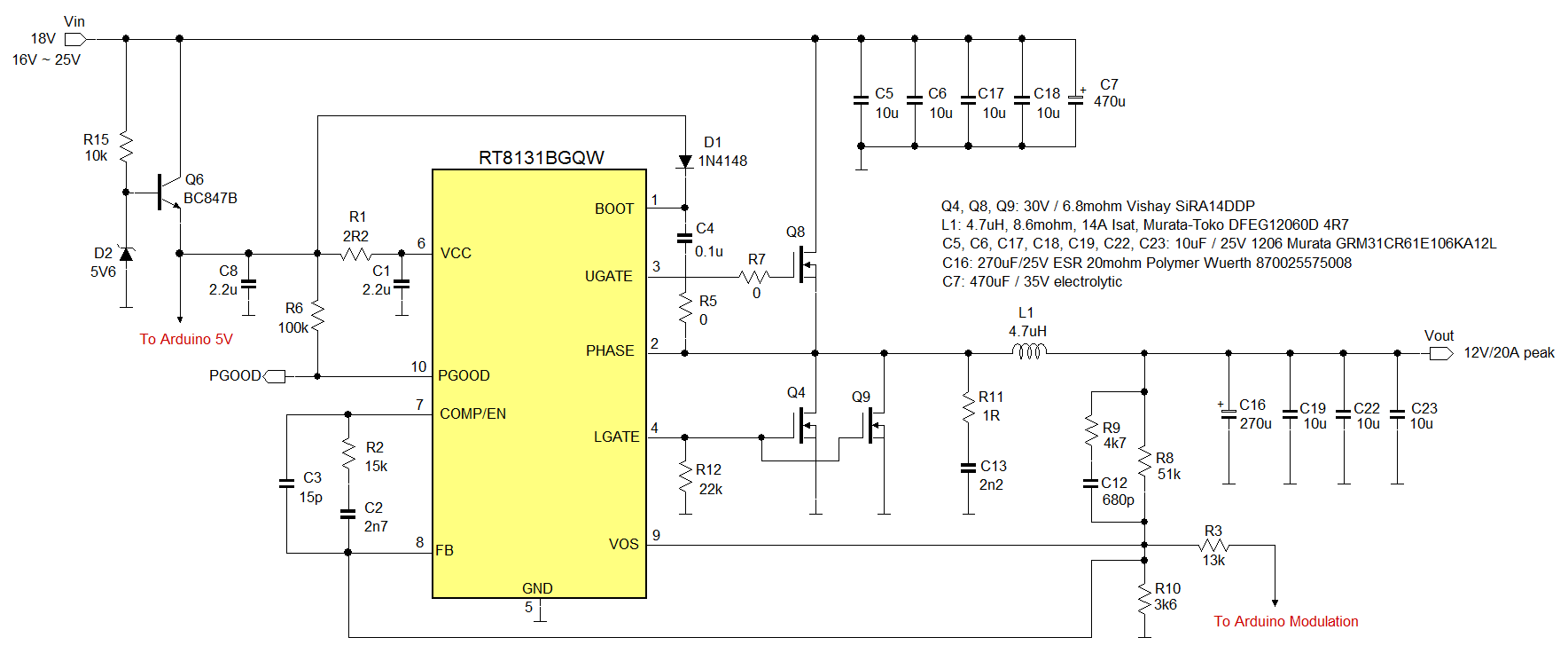
Figure 5
For 12V output, the input voltage should be at least 16V. The compensation network has been calculated based on the output capacitor C16 ESR. The VOS pin has the same connection as the FB pin to achieve the largest OVP window to avoid false trigger with fast changing feedback modulation signals. Two low-side MOSFETs were used to increase the OCP trigger level during positive and negative output voltage slew-rate.
The Arduino Nano MCU board will be powered from the same supply as the RT8131B VCC 5V supply, which is derived from the RT8131B input voltage via a simple transistor regulator Q6.
The Arduino circuit is shown in figure 6.
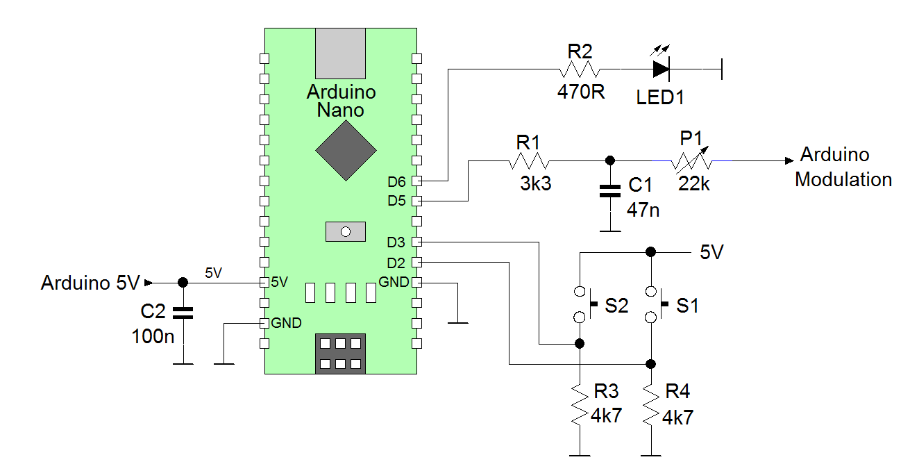
Figure 6
The Arduino Pin D5 is used as PWM output and Pin D6 is used as LED driver output. Pins D2 and D3 are used as inputs for the two pushbutton switches. Pressing S2 will run one cold crank profile, pressing S1 will run 30 profiles with 1.5sec in between.
For the cold-crank waveform, an actual measurement was used to derive a simulation waveform.
Figure 7 shows the black measured waveform and the red simulation waveform.
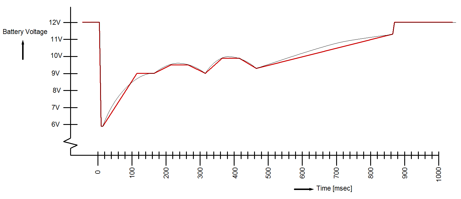
Figure 7
Standard Arduino PWM frequency on Pin D5 is 980Hz, but this low frequency will require a low pass filter with relatively low 3dB frequency, which makes it difficult to obtain fast changing output voltage fluctuations. For this design, a special command was used to set the Arduino pin D5 PWM frequency at 62.5kHz, which makes it possible to use a low pass filter with 1kHz 3dB frequency, which allows fast changing modulation voltage.
The PWM generated cold crank is the inverse of the Buck converter output waveform. The simulation PWM waveform is shown in figure 8, and was the base for the Arduino PWM programming (8 bit resolution).
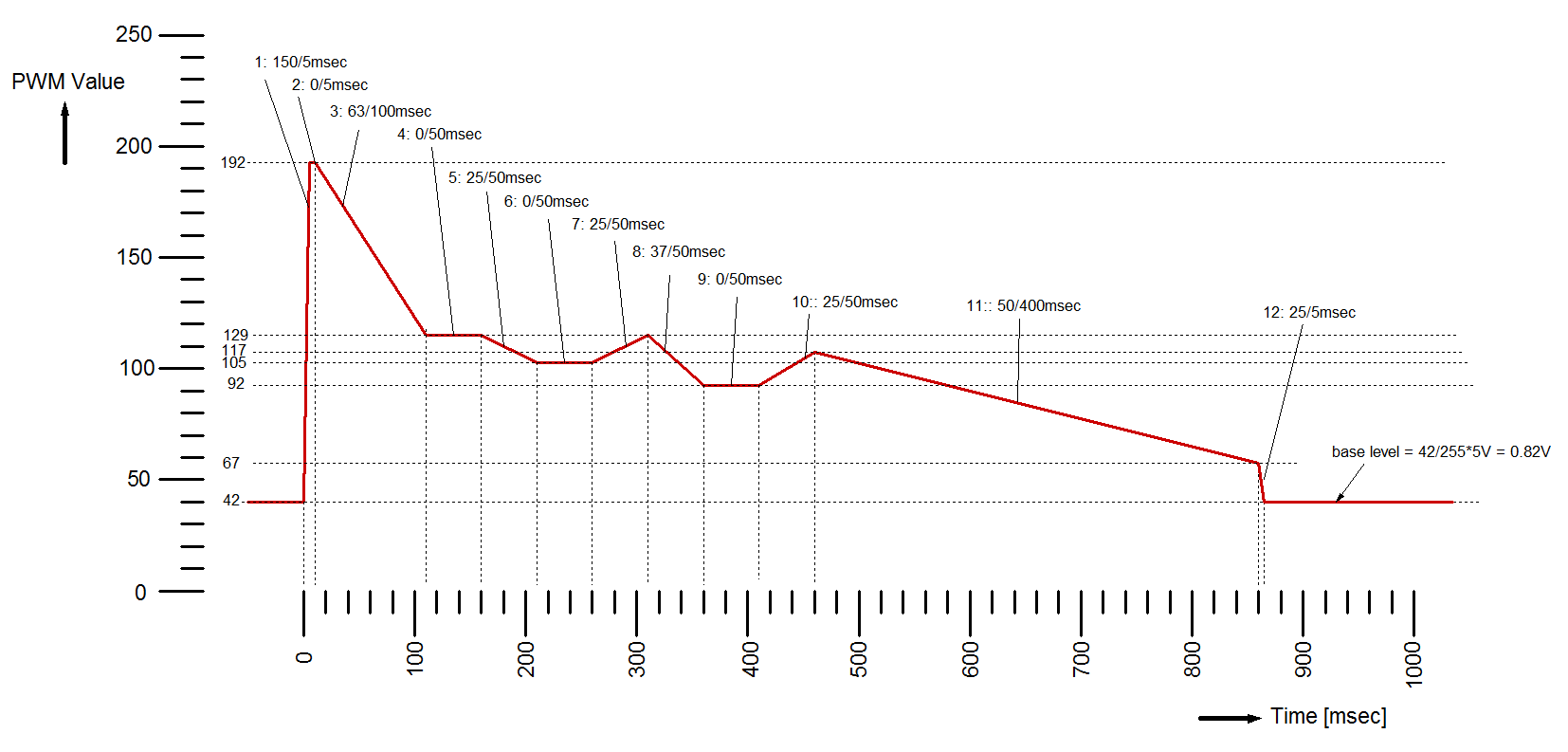
Figure 8
The PWM base level is set at around the RT8131B feedback reference of 0.8V: in this way the base level will not shift when the modulation is increased by reducing the variable resistor P1.
4.
Arduino program
The Arduino code for this project is quite simple, it can be copied and pasted directly into the Arduino sketch.
// Program for Arduino Nano for self-made car battery cold-crank waveform generator in combination with RT8131BGQW Buck controller
// Roland van Roy, Richtek Europe FAE January 2021
void setup() {
TCCR0B = TCCR0B & B11111000 | B00000001; // for PWM frequency of 62500.00 Hz, note delay(1) gives 15.8usec delay
pinMode(5,OUTPUT); // PWM output on pin 5
pinMode(6, OUTPUT); // LED mounted on pin 6
pinMode(3, INPUT); // switch mounted on pin 3
pinMode(2, INPUT); // switch mounted on pin 2
analogWrite(5, 42); //set PWM for 0.8V initial output
}
void loop() {
if (digitalRead(3)== HIGH){ // run 1 time profile
profile();
}
if (digitalRead(2)==HIGH){ // run 30 times profile with
1.5 sec in between
for (int i = 1; i<=30; i=i+1){
profile();
delay(32000); //0.5sec
delay(32000); //0.5sec
delay(32000); //0.5sec
}
}
}
void profile() { // crank profile subroutine
digitalWrite(6,HIGH); // LED ON
//step1
for (int i = 42; i <= 192; i=i+1) {
analogWrite(5, i);
delay(1); //150 steps in 1*15.8usec = 2.37msec but will be ~ 5msec when including program delay
}
//step2
delay(315); // delay 5msec
// step3
for (int i = 192; i >= 129; i=i-1) {
analogWrite(5, i);
delay(100); //63 steps in 100*15.8usec = 100msec
}
// step4
delay(3150); //50msec
// step5
for (int i = 129; i >= 105; i=i-1) {
analogWrite(5, i);
delay(126); //25 steps in 126*15.8usec = 50msec
}
// step6
delay(3150); //delay 50msec
// step7
for (int i = 105; i <= 129; i=i+1) {
analogWrite(5, i);
delay(126); //25 steps in 126*15.8usec = 50msec
}
// step8
for (int i = 129; i >= 92; i=i-1) {
analogWrite(5, i);
delay(85); //37 steps in 85*15.8usec = 50msec
}
// step9
delay(3150); //50msec
// step10
for (int i = 92; i <= 117; i=i+1) {
analogWrite(5, i);
delay(126); //25 steps in 126*15.8usec = 50msec
}
// step11
for (int i = 117; i >= 67; i=i-1) {
analogWrite(5, i);
delay(504); //50 steps in 504*15.8usec = 400msec
}
// step12
for (int i = 67; i >= 42; i=i-1) {
analogWrite(5, i);
delay(13); //25 steps in 13*15.8usec = 5msec
}
digitalWrite(6,LOW); // LED OFF
}
5.
Using the cold crank voltage generator
The cold crank voltage profile generator can be used to test various devices, like automotive pre-converters, automotive POC camera systems, automotive USB type-C chargers, etc. Simply connect an 18V supply to the RT8131B input, connect the Arduino board to the RT8131B EVB GND, VCC and feedback Modulation input, then connect the device under test to the RT8131B output.
Figure 9 shows a measurement setup for testing the cold-crank behavior of the RTQ2104GSP 36V rated 5V/3A output automotive buck converter: its input is connected to the RT8131B output and the 5V output is connected to a 3A load.
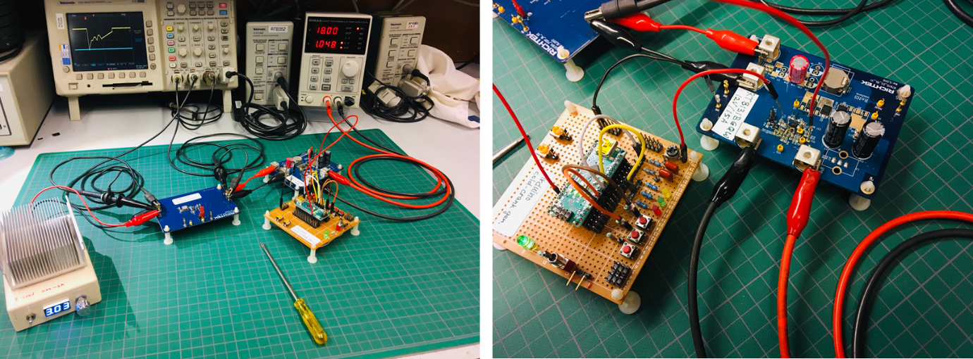
Figure 9
For this example, the cold crank waveform modulation was adjusted by the variable resistor to set the voltage dip at exactly the RTQ2104BGSP-QA buck converter 5V output. From the measurement shown in figure 10, it can be seen that the buck converter output (bottom waveform CH2) shows a very slight voltage dip when the converter input voltage approaches the output voltage: This buck converter supports high duty-cycle operation, so the dropout voltage at VIN = VOUT is very small.
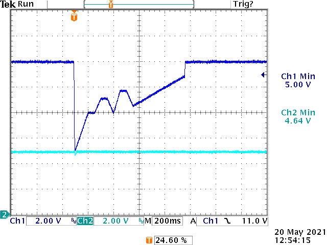
Figure 10
6.
Summary
For testing automotive pre-converters, testing with dynamic changing input voltage is mandatory to make sure the system can work correctly during car battery voltage changes like during cold cranking. It is not difficult to build a car battery cold crank voltage generator by using an Arduino and a high current CCM buck converter, which is a handy tool to test the fluctuating input voltage behavior
of various converter circuits.